Eureka AIR delivers breakthrough ideas for toughest innovation challenges, trusted by R&D personnel around the world.

A Cylindrical Grinding Device Applicable to Shafts with Different Diameters

A technology of cylindrical grinding and different diameters, which is applied in the direction of grinding devices, grinding drive devices, grinding machine tools, etc., which can solve the problem that the center distance of the supporting wheel and the height of the supporting wheel cannot be adjusted and moved, reduce the grinding accuracy of the device, and reduce the application of the grinding machine. In order to improve the applicability and work stability, improve the grinding accuracy and ensure the positioning

Inactive Publication Date: 2020-10-09
湖州甬邦纺织品织造有限公司
View PDF7 Cites 0 Cited by
  • Summary
  • Abstract
  • Description
  • Claims
  • Application Information

AI Technical Summary

Problems solved by technology

However, the supporting wheel structure of this type of grinding machine is in a fixed state, and the center distance of the supporting wheel and the height of the supporting wheel cannot be adjusted and moved. Causes problems that cannot be installed normally, reducing the applicability of the grinder
In addition, since the grinding head will cause the shaft parts to vibrate under force during grinding, conventional grinding machines generally reduce the vibration amplitude of the parts by limiting the shaft parts, but the way of limiting still makes the parts rotate When grinding, it is in a state of small vibration, which reduces the grinding accuracy of the device
Therefore, the existing grinding device has the problem that it cannot be applied to the grinding of shafts with different diameters, and the grinding accuracy is low.

Method used


Image

  • A Cylindrical Grinding Device Applicable to Shafts with Different Diameters
  • A Cylindrical Grinding Device Applicable to Shafts with Different Diameters

Examples


Embodiment Construction

[0012] The present invention will be further described below in conjunction with the drawings and embodiments, but it is not a basis for limiting the present invention.

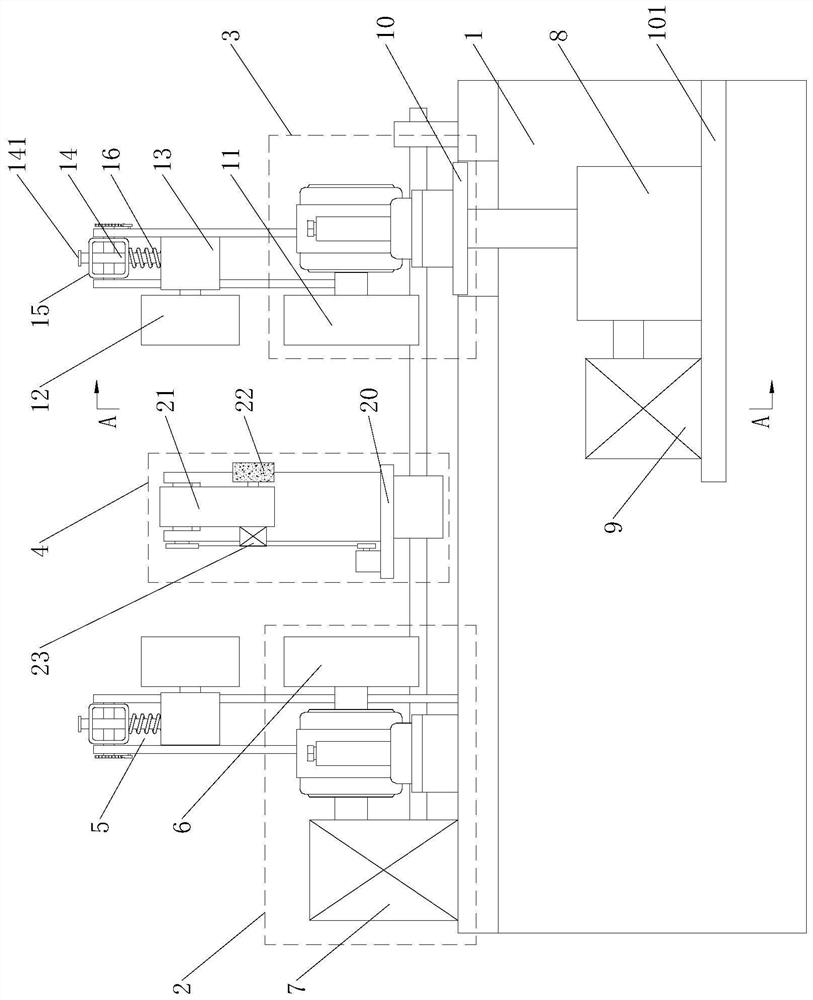
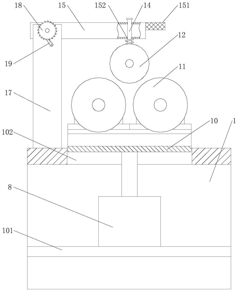
[0013] Examples. A cylindrical grinding device suitable for reducing shafts, composed as figure 1 As shown, it includes a worktable 1. Both ends of the top of the worktable 1 are respectively provided with a driving wheel set 2 and a driven wheel set 3, between the driving wheel set 2 and the driven wheel set 3, there is a grinding set located on the top side of the worktable 1 4. Both the driving wheel group 2 and the driven wheel group 3 are provided with a pressing wheel group 5; the driving wheel group 2 includes two first rotating wheels 6 arranged side by side on the worktable 1, one of which rotates first The end of the wheel 6 is connected with a drive motor 7. The driven wheel set 3 includes a horizontal plate 101 located below the workbench 1. The horizontal plate 101 is provided with a screw lift 8 an...


PUM


Abstract

The invention discloses a cylindrical grinding device suitable for reducing shafts. The cylindrical grinding device comprises a workbench, wherein two ends of the top of the workbench are provided with a driving wheel set and a driven wheel set respectively; a grinding set positioned on one side of the top of the workbench is arranged between the driving wheel set and the driven wheel set; one sides of the driving wheel set and the driven wheel set are each provided with a pressing wheel set correspondingly; the driven wheel set comprises a transverse plate positioned below the workbench; thetransverse plate is provided with a lead screw lifter; the top of the lead screw lifter is connected with a lifting table; the top of the lifting table is provided with two parallel second rotating wheels; the pressing wheel set comprises a pressing wheel; one end of the pressing wheel is rotatably connected to a connecting seat; the connecting seat is connected with a rotating arm through a roundrod; and a pressing spring positioned outside the round rod is arranged between the connecting seat and the rotating arm. The cylindrical grinding device is suitable for grinding reducing shafts andhas the characteristic of high grinding precision.

Description

Technical field [0001] The invention relates to a cylindrical grinding device, in particular to a cylindrical grinding device suitable for reducing shafts. Background technique [0002] Grinding machine is a grinding machine that uses a grinding tool coated or embedded with abrasives to grind the surface of a workpiece; it is mainly used to grind high-precision flat surfaces, inner and outer cylindrical surfaces, conical surfaces, spherical surfaces, threaded surfaces and other profiles in the workpiece. At present, most of the grinding methods for the outer cylindrical surface of shaft parts are to place the shaft parts on a rotatable supporting wheel. The supporting wheel drives the shaft parts to rotate and contact the grinding head, thereby realizing the grinding of the outer circle of the parts. However, the supporting roller structure of this type of grinding machine is in a fixed state, and the center distance of the supporting wheel and the height of the supporting wheel ...

Claims


Application Information

Patent Timeline
Patent Type & Authority Patents(China)
IPC IPC(8): B24B37/02B24B37/27B24B37/34B24B47/12
CPCB24B37/02B24B37/27B24B37/34B24B47/12
Inventor 方仲华
Owner 湖州甬邦纺织品织造有限公司
Why Eureka
Eureka Blog
Learn More