Light mixing, color mixing and light condensing light ray extraction apparatus for lighting

A technology of concentrators and extractors, which is applied in light guides of lighting devices, light guides of lighting systems, lighting devices, etc., can solve the problems of light mixing and poor color mixing effects, and achieve compact structure, small etendue, and simple small effect

Pending Publication Date: 2020-03-10
YANGLITE SHANGHAI TECH CO LTD
View PDF1 Cites 0 Cited by
  • Summary
  • Abstract
  • Description
  • Claims
  • Application Information

AI Technical Summary

Problems solved by technology

[0002] At present, the common light mixing and color mixing scheme is to use a compound parabolic concentrator, a light guide rod at the light source end or a pair of fly-eye lens groups. The compound parabolic concentrator can shrink the divergence angle of the light, and can For light mixing and color mixing, the light guide rod at the light source end is usually a slender optical device, and its cross-section can be any shape, so that the light propagates in it in a way of total reflection, because usually the light input end of the light guide rod at the light source end The size of the output end is different, and sometimes the shape is also different. In the document of patent No. 201721357695.4 previously applied by the company, two light-emitting crystals arranged in parallel or in series are provided. In this case, the compound parabolic concentrator It will lead to very poor light mixing and color mixing effects of the extracted light. In order to increase the light mixing, color mixing and light focusing effects, a reasonable light extractor should be designed

Method used


Image

  • Light mixing, color mixing and light condensing light ray extraction apparatus for lighting
  • Light mixing, color mixing and light condensing light ray extraction apparatus for lighting
  • Light mixing, color mixing and light condensing light ray extraction apparatus for lighting

Examples


no. 2 example

[0042] Such as Figure 8 As shown, the difference from the first embodiment is that this embodiment provides a light-mixing, color-mixing and concentrating light extractor for lighting, an optical device 201 is provided between the first light output end 103 and the second light input end, There is no optical contact between the optical device 201 and the second concentrator 104, and the two ends of the optical device 201 are respectively the third light input end connected to the first light output end 103 and the third light input end connected to the second light input end 105. At the light output end, the end face of the third light output end is a non-polished surface.

no. 3 example

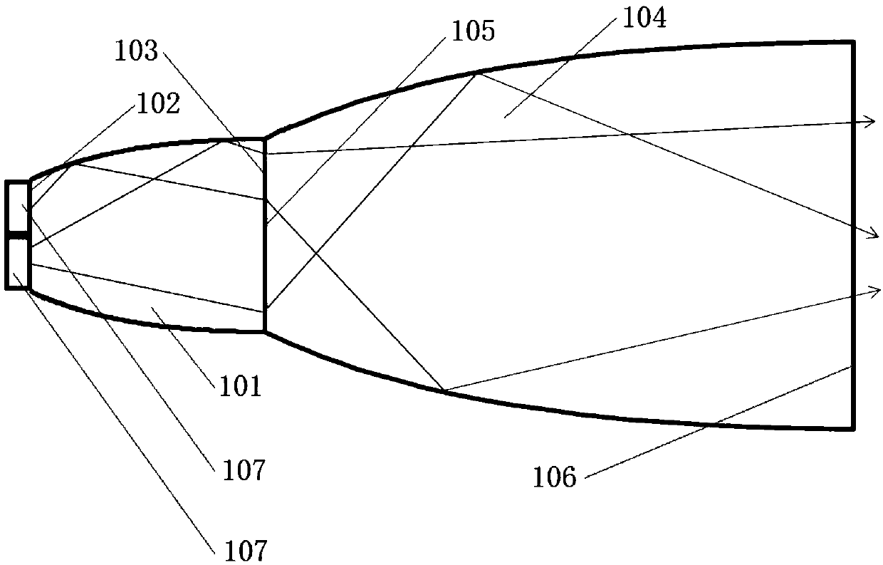
[0044] Such as Figure 9 As shown, the difference from the first embodiment is that two light-emitting crystals 107 are arranged in series on the side of the first light input end 102 away from the first concentrator 101 .

no. 4 example

[0046] Such as Figure 10 As shown, the difference from the first embodiment is that this embodiment provides a light-mixing, color-mixing, and concentrating light extractor for lighting, and a condenser The light guide rod 301 at the light collector end, and the two ends of the light guide rod 301 at the light collector end are respectively the fourth light input end 302 connected with the first light concentrator 101 and the fourth light output end connected with the second light concentrator 104 303 , the end surface of the fourth light output end 303 is a non-polished surface, and the light guide rod 301 at the concentrator end is a light guide rod.


PUM


Abstract

The invention discloses a light mixing, color mixing and light condensing light ray extraction apparatus for lighting. The light mixing, color mixing and light condensing light ray extraction apparatus comprises a light ray extractor arranged in a light emitting device, wherein luminous crystals are arranged in the light emitting device; the light ray extractor is connected to one end of the luminous crystals and used for extracting light rays emitted by the luminous crystals, mixing the light rays, mixing colors, condensing the light rays and then emitting the light rays out; the light ray extractor comprises a first condenser and a second condenser; two ends of the first condenser are correspondingly a first light ray input end connected to the luminous crystals, and a first light ray output end connected to the second condenser; the end, facing the first light ray output end, of the second condenser is a second light ray input end, while the other end of the second condenser is a second light ray output end; the first condenser and the second condenser have no optical contact; and the plurality of luminous crystals are arranged in parallel or in series on the side, far away fromthe first condenser, of the first light ray input end.

Description

technical field [0001] The invention relates to the technical field of lighting devices, in particular to a light-mixing, color-mixing, and condensing light extractor for lighting. Background technique [0002] At present, the common light mixing and color mixing scheme is to use a compound parabolic concentrator, a light guide rod at the light source end or a pair of fly-eye lens groups. The compound parabolic concentrator can shrink the divergence angle of the light, and can For light mixing and color mixing, the light guide rod at the light source end is usually a slender optical device, and its cross-section can be any shape, so that the light propagates in it in a way of total reflection, because usually the light input end of the light guide rod at the light source end The size of the output end is different, and sometimes the shape is also different. In the document of patent No. 201721357695.4 previously applied by the company, two light-emitting crystals arranged in...

Claims


Application Information

Patent Timeline
Patent Type & Authority Applications(China)
IPC IPC(8): F21S2/00F21V7/00F21V19/00F21V8/00
CPCF21S2/00F21V7/00F21V19/00F21V2200/00
Inventor 赫尔曼·范·贝尔科姆
Owner YANGLITE SHANGHAI TECH CO LTD
Why Eureka
Try Eureka