Lens and light source device with the same

A technology of light source device and lens, applied in the direction of light source, lighting device, point light source, etc., can solve the problems of multi-volume, general products without structure, power consumption, etc.

Inactive Publication Date: 2009-06-10
BRIGHT LED ELECTRONICS CORP
View PDF0 Cites 10 Cited by
  • Summary
  • Abstract
  • Description
  • Claims
  • Application Information

AI Technical Summary

Problems solved by technology

[0002] The conventional direct-lit backlight module uses cold cathode fluorescent lamps (Cold Cathode Fluorescent Lamp, CCFL) as the light source. It has become the current development trend to use light-emitting diodes with small size, high luminous efficiency and long life as light sources.
[0003] However, because the light-emitting diode is like a point light source when it emits light, please refer to Figure 1, which is a polar coordinate diagram of light intensity, which shows that the conventional light-emitting diode is like a point light source when it emits light, that is, in the same way as the light-emitting surface The light intensity in the direction of 0° of the line clip is the largest, and the light intensity in the direction that deviates from the normal line decreases gradually. Therefore, a light spot will be clearly seen on the light-emitting surface, and it cannot provide illumination with uniform light intensity distribution.
[0004] It can be seen that the above-mentioned existing light-emitting semiconductor elements obviously still have inconvenience and defects in structure and use, and need to be further improved urgently.
In order to solve the above-mentioned problems, the relevant manufacturers have tried their best to find a solution, but no suitable design has been developed for a long time, and the general products do not have a suitable structure to solve the above-mentioned problems. This is obviously related. The problem that the industry is eager to solve

Method used


Image

  • Lens and light source device with the same
  • Lens and light source device with the same
  • Lens and light source device with the same

Examples


Embodiment Construction

[0049] In order to further explain the technical means and effects that the present invention adopts to achieve the intended purpose of the invention, below in conjunction with the accompanying drawings and preferred embodiments, the specific implementation, structure, Features and their functions are described in detail below.

[0050] The aforementioned and other technical contents, features and effects of the present invention will be clearly presented in the following detailed description of preferred embodiments with reference to the drawings. Through the description of the specific implementation mode, when the technical means and functions adopted by the present invention to achieve the predetermined purpose can be obtained a deeper and more specific understanding, but the accompanying drawings are only for reference and description, and are not used to explain the present invention be restricted.

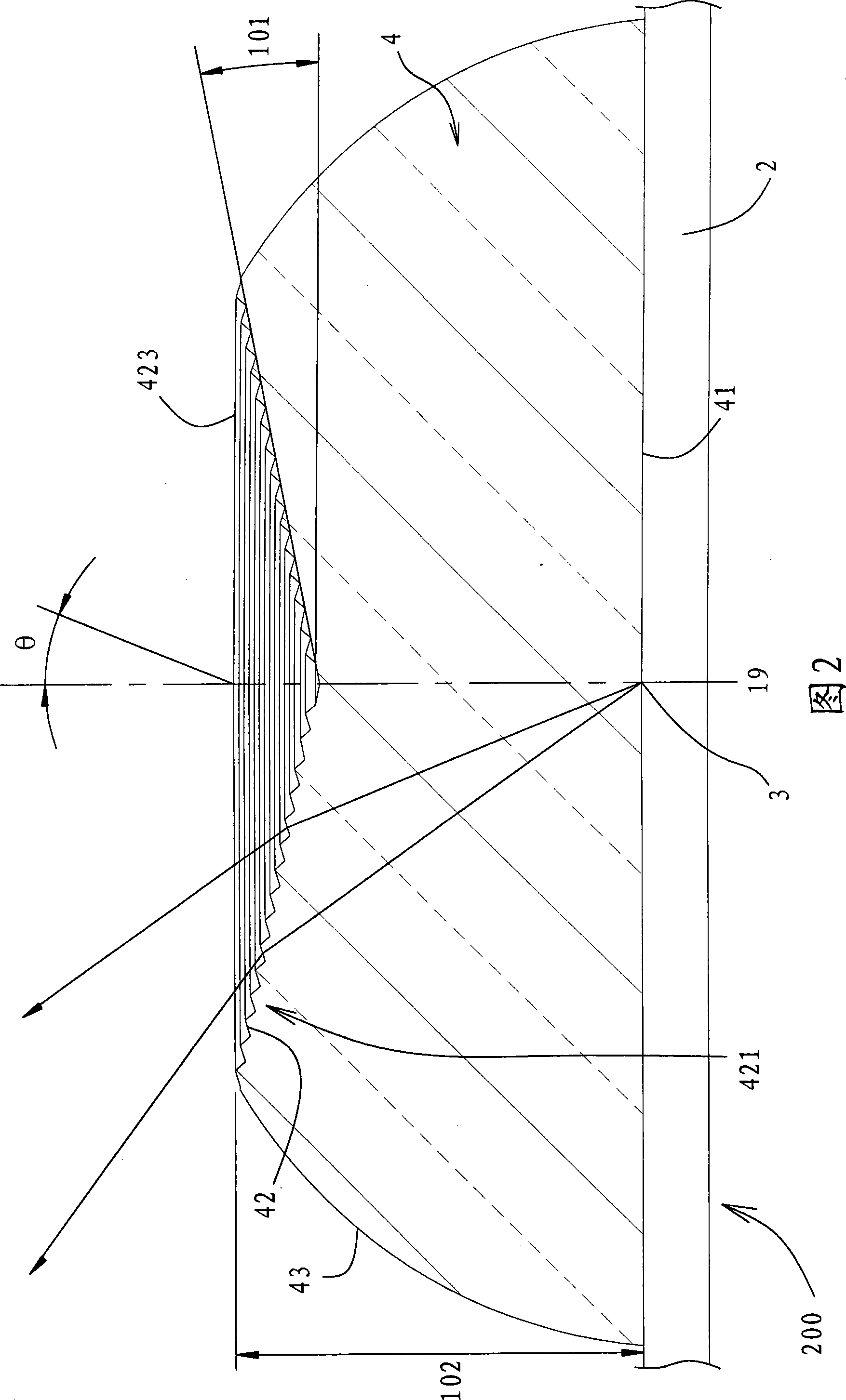
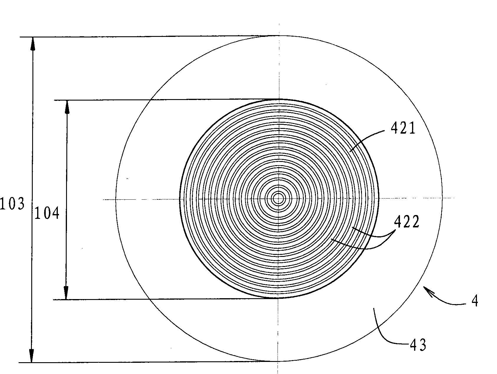
[0051] Please refer to Figure 2, image 3 and Figure 4 As shown, Fig...


PUM


Abstract

The invention provides a lens and a light source device with the lens; wherein, the lens which is used for receiving light rays given out by a luminous semiconductor component comprises a bottom surface, a top surface and a side surface; the bottom surface is opposite to the luminous semiconductor component to receive light rays; the top surface is reversed to the bottom surface and comprises a rough surface structure which causes part of light rays which go through the bottom surface and is incident to the top surface instead of going to the right above of the top surface; the side surface extends to the peripheral part of the bottom surface form the peripheral part of the top surface and the light rays which go through the bottom surface and are incident to the side surface are irradiated out of the lens; the shape of the lens is gradually enlarged from the junction of the top surface and the side surface to the direction of the bottom surface; a projection of the section at the upper part of the lens falls into the scope of the section of the lower part of the lens. The lens and the light source device can cause intensity of light rays given out by the luminous semiconductor component to be distributed evenly and therefore light fields with even distribution of the light intensity can be obtained on an exit aperture.

Description

technical field [0001] The invention relates to a lens and a light source device with the lens, in particular to a lens that can make the light intensity distribution of light emitted by a light-emitting diode uniform on a light exit surface and a light source device with the lens. Background technique [0002] The conventional direct-lit backlight module uses cold cathode fluorescent lamps (Cold Cathode Fluorescent Lamp, CCFL) as the light source. It has become a current development trend to use light-emitting diodes with small volume, high luminous efficiency and long life as light sources. [0003] However, because the light-emitting diode is like a point light source when it emits light, please refer to Figure 1, which is a polar coordinate diagram of light intensity, which shows that the conventional light-emitting diode is like a point light source when it emits light, that is, in the same way as the light-emitting surface The light intensity in the direction of 0° of...

Claims


Application Information

Patent Timeline
Patent Type & Authority Applications(China)
IPC IPC(8): F21V5/04F21Y101/02
Inventor 陈亮棠张铭利殷寿志
Owner BRIGHT LED ELECTRONICS CORP
Why Eureka
Try Eureka