Infrared Generating Network

An infrared and mesh technology, applied in the burner, combustion type, combustion method, etc., can solve the problems of inability to effectively increase the infrared scattering surface area, increase the fire temperature, and inability to increase the infrared scattering range and intensity.

Active Publication Date: 2021-07-06
GRAND MATE
View PDF8 Cites 0 Cited by
  • Summary
  • Abstract
  • Description
  • Claims
  • Application Information

AI Technical Summary

Problems solved by technology

However, ceramic combustion plates 2 are generally planar plates, which cannot effectively increase the scattering surface area of ​​infrared rays, and cannot increase the scattering range and intensity of infrared rays.
Therefore, it is impossible to further increase the attainable fire temperature of the combustion device that generates the infrared heat source
[0004] Therefore, its design of the existing combustion device 1 that produces the infrared heat source still needs to be improved.

Method used


Image

  • Infrared Generating Network
  • Infrared Generating Network
  • Infrared Generating Network

Examples


Embodiment Construction

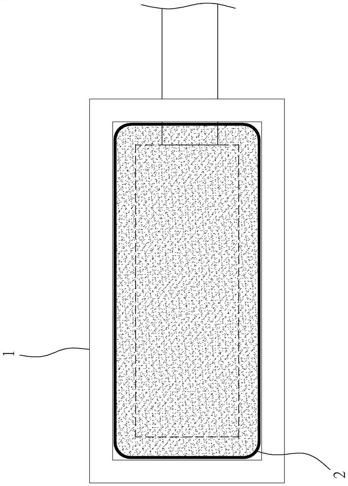
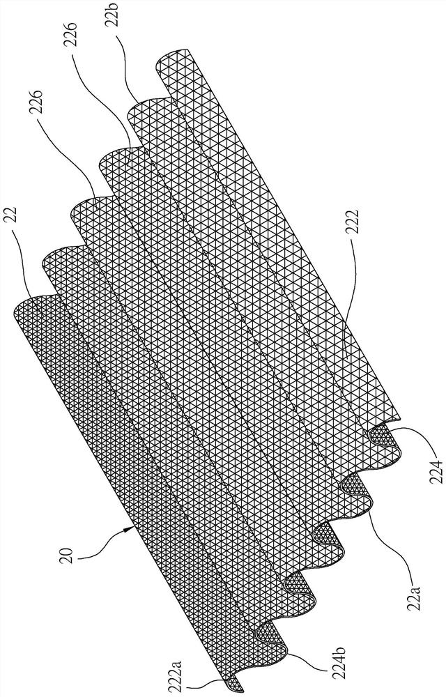
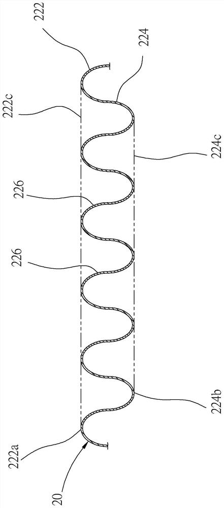
[0023] In order to illustrate the present invention more clearly, preferred embodiments are given and detailed descriptions are given below in conjunction with drawings. Please refer to Figure 2 to Figure 3 Shown is the infrared ray generating net 20 of the first preferred embodiment of the present invention

[0024] Such as figure 2 As shown, the infrared generating net 20 is made of metal, which is iron-chromium-aluminum alloy in this embodiment. The infrared generating net comprises a rectangular mesh body 22, which has a first surface 222 and a second surface 224 opposite to each other, and a periphery; the first surface 222 is not shielded and exposed to the outside , the peripheral edge has four edges, and two opposite edges form a first portion 22a and a second portion 22b. In actual production, the periphery of the mesh body 22 can also be circular, and the periphery of the mesh body 22 can be divided into two halves with a circular diameter, wherein the first par...


PUM


Abstract

An infrared ray generating net, its burning device includes at least one burner, a support component, an infrared reflective plate, and an infrared ray generating net; wherein, the at least one burner has a fire outlet; the infrared ray generating net is set on the support on the component, and is heated by the flame generated by the fire outlet to generate infrared rays; the support component includes a rear shield, and the infrared reflector is arranged between the rear shield and the infrared reflector, and the infrared reflector reflects the infrared generating net Incident infrared rays; thereby, an infrared heat source is generated to effectively increase the heating intensity and achieve the purpose of uniform heating.

Description

【Technical field】 [0001] The present invention relates to heating equipment; in particular, it refers to an infrared generating net used in an infrared burning device. 【Background technique】 [0002] In combustion devices, the common way to supply heat is to heat the heated object through an open flame. However, when an object is heated, the heat conduction path is through the surface of the object to the interior of the object, and therefore, the object will be heated unevenly. For example, when food is heated, the outer surface of the food will first be heated by the heat generated by the open fire, and then the heat will be gradually transferred to the inside of the food. As a result, the surface of the food is often overcooked, but the inside is still undercooked. [0003] Therefore, combustion devices that generate infrared heat sources have been developed on the market to solve the problem of uneven heating of objects. Yet, in the combustion device 1 that generally p...

Claims


Application Information

Patent Timeline
Patent Type & Authority Patents(China)
IPC IPC(8): F23D14/84
CPCF23D14/84F23D2203/1017
Inventor 黃重景黃锦颖黄信铭黃信雄叶严仁林冠州
Owner GRAND MATE
Why Eureka
Try Eureka