Photovoltaic system and method of switching output state of photovoltaic system

A photovoltaic system and photovoltaic technology, applied in the field of photovoltaic systems, can solve problems such as the lack of intelligent rapid shutdown of photovoltaic systems, and achieve the effect of ensuring personal safety

Pending Publication Date: 2020-03-10
CSI CELLS CO LTD +2
View PDF0 Cites 1 Cited by
  • Summary
  • Abstract
  • Description
  • Claims
  • Application Information

AI Technical Summary

Problems solved by technology

However, there is still a gap in the market for fast shutdown photovoltaic systems
[0003] Based on the above analysis, there is a lack of an intelligent and fast shutdown photovoltaic system in the existing technical solutions

Method used


Image

  • Photovoltaic system and method of switching output state of photovoltaic system
  • Photovoltaic system and method of switching output state of photovoltaic system
  • Photovoltaic system and method of switching output state of photovoltaic system

Examples


Embodiment 2

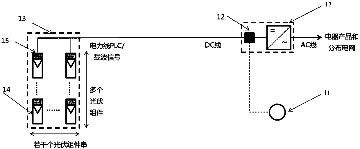
[0059] see Figure 4 As shown, the embodiment of the present application provides a photovoltaic system, which includes a transmitter 11 and two photovoltaic subsystems, wherein each photovoltaic subsystem includes a communicator 12, a photovoltaic module string array 13, and each photovoltaic module string The array 13 includes several photovoltaic modules 14 and several receivers 15 , wherein the photovoltaic modules 14 are connected to the receivers 15 in a one-to-one correspondence. The transmitter 11 is used to send a communication signal to turn off or turn on the photovoltaic module 14, the communicator 12 is connected to the transmitter 11 to transmit the communication signal sent by the transmitter 11, and the receiver 15 is used to receive the communicator 12 to transmit the communication signal, and then change the output state of the photovoltaic module 14 according to the communication signal.

[0060] It can be seen that the two photovoltaic subsystems respectiv...

Embodiment 3

[0065] see Figure 5 As shown, the embodiment of the present application provides a method for switching the output state of a photovoltaic system, including:

[0066] Step S1, the transmitter sends a communication signal to turn off or turn on the photovoltaic module;

[0067] In the embodiment of the present application, the transmitter may be a manual switch device or an automatic switch device, which has been described in detail in the previous embodiment and will not be repeated here.

[0068] Step S2, the communicator receives the communication signal sent by the transmitter and transmits the communication signal;

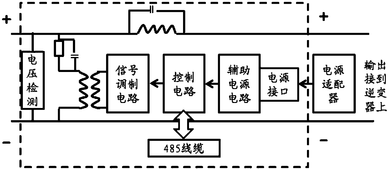
[0069] When the communicator receives the communication signal sent by the transmitter, it transmits the communication signal in the form of a carrier wave, specifically:

[0070] After receiving the communication signal sent by the transmitter, the control circuit of the transmitter transmits it to the modulation circuit, and the modulation circuit modulat...


PUM


Abstract

The invention provides a photovoltaic system and a method of switching the output state of the photovoltaic system. The photovoltaic system comprises an emitter and a plurality of photovoltaic subsystems, wherein each photovoltaic subsystem comprises a transmitter, a plurality of photovoltaic assemblies and a plurality of receivers; the emitter is used for sending a communication signal for turning off or turning on the photovoltaic module; the transmitters are all connected with the emitter and are used for transmitting the communication signals sent by the emitter; the receivers are connected with the photovoltaic assemblies in a one-to-one correspondence mode and used for receiving the communication signals transmitted by the transmitter and changing the output states of the photovoltaic assemblies according to the communication signals. By adopting the technical scheme of the invention, when a photovoltaic power station in the photovoltaic subsystem has a safety problem such as a fire, the communication signals can be sent by the emitter, the output state of the photovoltaic module connected with the receiver is further controlled, and thus, through operating the emitter, the output state of the photovoltaic system is further timely switched, and the operation is completed on the premise of guaranteeing the personal safety of related personnel.

Description

technical field [0001] The present application relates to the technical field of photovoltaic systems, in particular to a photovoltaic system and a method for switching an output state of the photovoltaic system. Background technique [0002] Due to the rapid development of photovoltaic module technology and the rapid growth of market demand for photovoltaic modules, solar photovoltaic power plants distributed in global regions have emerged as the times require, which meets the market demand to a certain extent. However, with the increase in the number of solar photovoltaic power plants, the safety of solar photovoltaic power plants has become a thorny issue. For example, when a fire breaks out in a photovoltaic power station due to safety issues in solar photovoltaic power stations, the voltage of the photovoltaic module system is relatively large, sometimes even as high as 1500V, which brings a lot of inconvenience to firefighters. The safe and reliable way is to quickly r...

Claims


Application Information

Patent Timeline
Patent Type & Authority Applications(China)
IPC IPC(8): H02S40/36H02J13/00H02J3/38
CPCH02S40/36Y02E10/50Y04S10/123Y02E40/70
Inventor 邓士锋董经兵刘亚锋邢国强
Owner CSI CELLS CO LTD
Why Eureka
Try Eureka