Device capable of randomly adjusting horizontal rigidity and adapting to wind resistance and shock insulation

A technology to adjust the level and stiffness, which is applied in the direction of earthquake resistance, building components, building types, etc., can solve the problems of unfavorable wind resistance of structures, and achieve the effect of reducing earthquake energy

Pending Publication Date: 2020-03-13
ARCHITECTURAL DESIGN & RES INST OF SOUTH CHINA UNIV OF TECH
View PDF0 Cites 2 Cited by
  • Summary
  • Abstract
  • Description
  • Claims
  • Application Information

AI Technical Summary

Problems solved by technology

[0011] In addition, although the small horizontal stiffness of the isolation bearing is beneficial to the isolation, it is unfavorable to the wind resistance of the structure

Method used

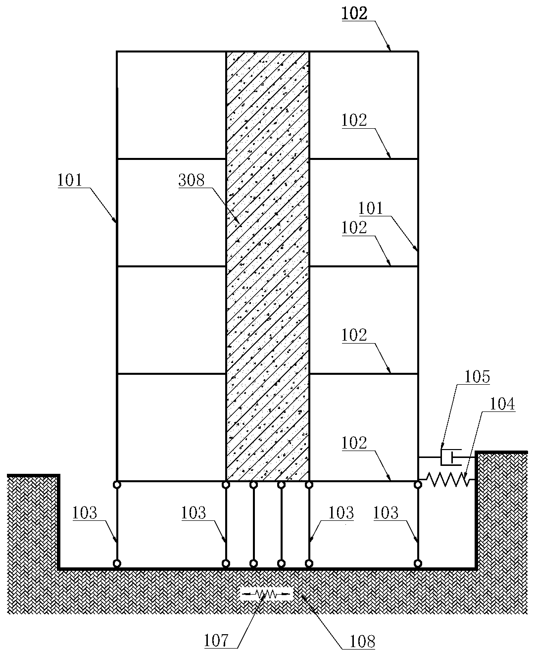
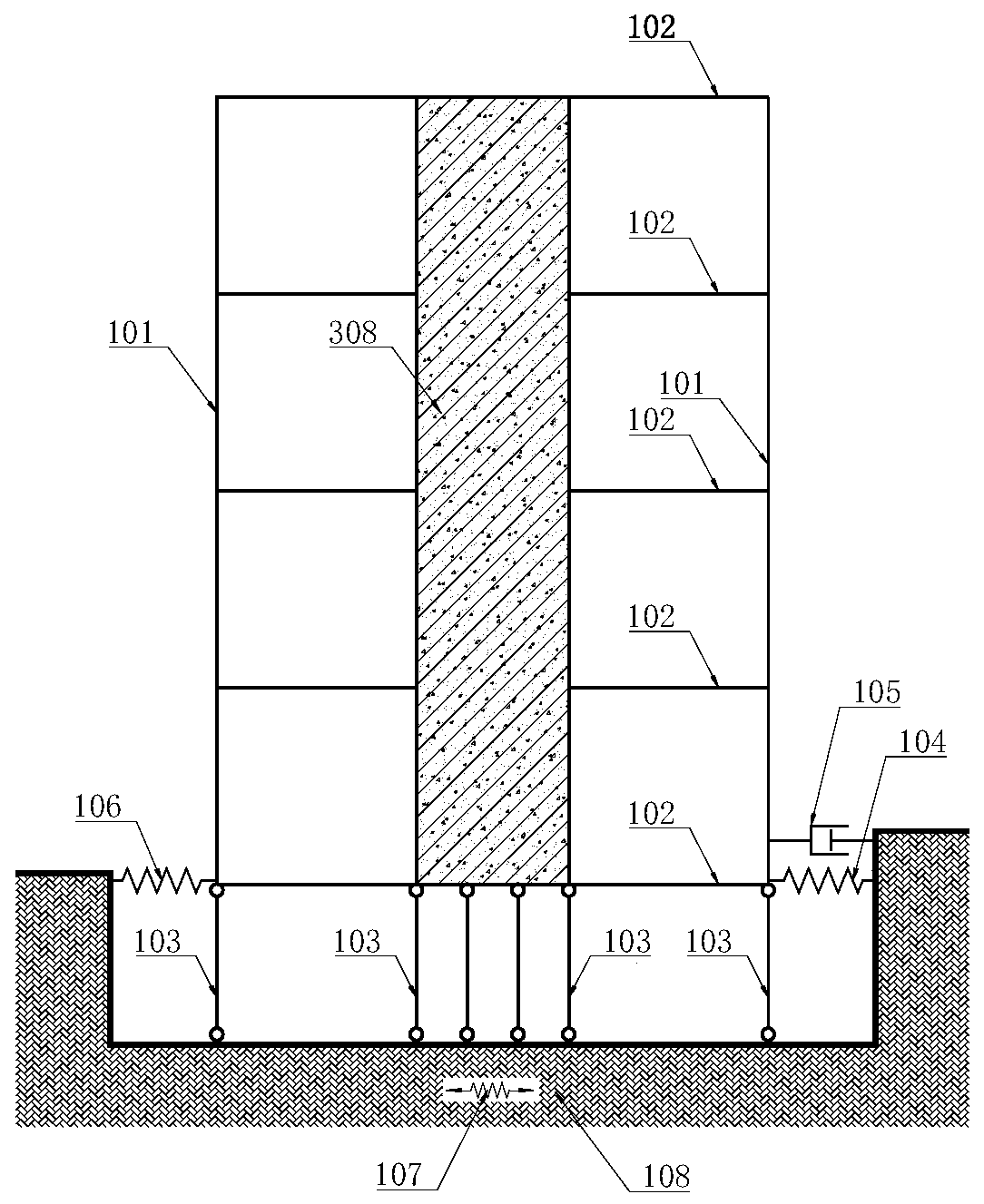
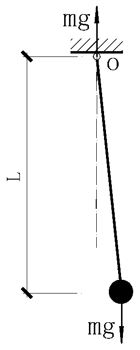

Image

  • Device capable of randomly adjusting horizontal rigidity and adapting to wind resistance and shock insulation
  • Device capable of randomly adjusting horizontal rigidity and adapting to wind resistance and shock insulation
  • Device capable of randomly adjusting horizontal rigidity and adapting to wind resistance and shock insulation

Examples


Embodiment 1

[0137] Such as Figure 19 , Figure 20 , a seismic isolation support column 304 formed by incomplete hemispherical splicing to provide vertical support and horizontal stiffness for the upper structure, using prestressed cables 309 to provide vertical tension for the upper structure, and using the maintenance structure 401 of the seismic isolation layer , 402 as the shock-isolation structure of variable stiffness mechanism.

[0138] Under each column 301, there is a seismic isolation support composed of a seismic isolation support column 304, a prestressed cable 309, upper and lower embedded parts 307, 306, and node force transmission components 302. The number of seismic isolation supporting columns 304 of each seismic isolation bearing is not less than 3 so as to effectively transfer the vertical loads borne by columns and shear walls to the substructure or foundation 108 . If the column supported by the seismic isolation support column has no tensile force, the correspondi...

Embodiment 2

[0142] Except that the method for realizing the variable stiffness of the shock-isolation layer is different from that of the first embodiment, the remaining parts are the same as the first embodiment.

[0143] In this embodiment, the abrupt change in stiffness is realized by using the ground acceleration to trigger the sudden change in stiffness control device.

[0144] Figure 21 ~ Figure 39 It is a schematic diagram of the abrupt change mechanism of the shock-isolation layer stiffness in this embodiment.

[0145] Such as Figure 21 In the plan view of the seismic isolation layer shown, the lower shear wall 501 is set at the position corresponding to the upper shear wall. The periphery of the lower shear wall 501 is provided with a seismic isolation support column 304 to withstand the pressure of the upper shear wall 308 . The periphery of the lower shear wall 501 is also provided with prestressed cables 309 to withstand the tension of the upper shear wall 308 .

[0146]...

Embodiment 3

[0151] Except that the triggering method for realizing the variable stiffness is different from that of the second embodiment, the other parts are the same as the second embodiment.

[0152] In this embodiment, the ordinary normally closed trigger valves 603L and 603R in the second embodiment are replaced with electromagnetic normally closed trigger valves 803L and 803R. The electromagnetic driving coil on the electromagnetic normally closed trigger valve 803L is 802L. When the electromagnetic driving coil 802L is not energized, the electromagnetic normally closed trigger valve 803L is closed. When the electromagnetic drive coil energizes 802L, the electromagnetic normally closed trigger valve 803L opens. The electromagnetic driving coil on the electromagnetic normally closed trigger valve 803R is 802R. When the electromagnetic driving coil 802R is not energized, the electromagnetic normally closed trigger valve 803R is closed. When the electromagnetic drive coil energizes ...


PUM


Abstract

The invention discloses a device capable of randomly adjusting horizontal rigidity and adapting to wind resistance and shock insulation. The device comprises a shock insulation layer which is arrangedbetween an upper structure and a lower structure and is composed of a plurality of shock insulation supporting bases and a plurality of horizontal rigidity mutation control devices, wherein the shockinsulation supporting bases are arranged below columns and shear walls of the upper structure, and provide vertical bearing force and horizontal rigidity for the columns and the shear walls of the upper structure, the horizontal rigidity mutation devices are arranged below the upper shear walls, under the action of wind loads, horizontal rigidity and horizontal bearing force provided by the horizontal rigidity mutation devices can effectively convey the wind loads to the lower structure or a foundation, and horizontal rigidity mutation of the horizontal rigidity mutation control devices is zero under the effect of an earthquake, so that the shock insulation layer plays a shock insulation effect. According to the device, a rigidity mutation control mechanism is formed by utilizing a maintenance structure of the shock insulation layer, or a mechanical principle, a hydraulic technology and an automatic control technology are used for adjusting and controlling the horizontal rigidity of the structure, the rigidity mutation is realized, and the purpose of effectively insulating the earthquake and resisting the wind loads is achieved.

Description

technical field [0001] The invention relates to the field of wind resistance and shock isolation, in particular to a device capable of arbitrarily adjusting the horizontal stiffness and adapting to wind resistance and shock isolation. Background technique [0002] The calculation model of the isolated structure is as follows: figure 1 shown. The upper structure is composed of several beams 102, several columns 101, and several shear walls 308 and the like. Several vertical connecting rods 103 provide vertical rigidity and vertical bearing capacity for the upper structure. The generalized horizontal spring 104 provides the upper structure with the required horizontal stiffness and horizontal bearing capacity to maintain the stability of the upper structure. 105 is a horizontal damper accompanied by a horizontal spring 104 . [0003] During an earthquake, the ground moves horizontally and vertically. The main thing that causes damage to buildings is the horizontal movemen...

Claims


Application Information

Patent Timeline
Patent Type & Authority Applications(China)
IPC IPC(8): E04H9/02E04H9/14E04B1/98
CPCE04B1/98E04H9/021E04H9/14
Inventor 舒宣武
Owner ARCHITECTURAL DESIGN & RES INST OF SOUTH CHINA UNIV OF TECH
Why Eureka
Try Eureka