
Building temperature control method and system based on model predictive control

A technology of model predictive control and temperature control method, which is applied in heating systems, heating methods, and household heating, etc., and can solve problems such as decreased thermal comfort of users, failure to consider future weather forecasts, and energy waste.

Inactive Publication Date: 2020-03-13
UNIV OF JINAN
View PDF6 Cites 7 Cited by
  • Summary
  • Abstract
  • Description
  • Claims
  • Application Information

AI Technical Summary

Problems solved by technology

[0003] At present, the heating temperature of the heat exchange station is mostly adjusted by the operator based on experience and the current outdoor temperature. When the outdoor temperature drops, the water supply temperature is increased, and when the outdoor temperature rises, the water supply temperature is lowered. The heating effect depends on the professional experience of the operator. The degree of automation and intelligence is low, and it is an open-loop control method
In addition, since the heating system has a large time constant, and the operator does not take into account the forecast of future weather when setting the heating temperature, it may take a long time for the indoor temperature to stabilize within the comfortable range after the water supply temperature is adjusted, and it is likely that It will cause underheating or overheating, resulting in a decrease in thermal comfort for users or unnecessary waste of energy

Method used


Image

  • Building temperature control method and system based on model predictive control
  • Building temperature control method and system based on model predictive control
  • Building temperature control method and system based on model predictive control

Examples


Embodiment Construction

[0082] Below in conjunction with accompanying drawing and embodiment the present invention will be further described:

[0083] In order to clearly illustrate the technical features of this solution, the present invention will be described in detail below through specific implementation modes and in conjunction with the accompanying drawings. The following disclosure provides many different embodiments or examples for implementing different structures of the present invention. To simplify the disclosure of the present invention, components and arrangements of specific examples are described below. Furthermore, the present invention may repeat reference numerals and / or letters in different instances. This repetition is for simplicity and clarity and does not in itself indicate a relationship between the various embodiments and / or arrangements discussed. It should be noted that components illustrated in the figures are not necessarily drawn to scale. Descriptions of well-known...


PUM


Abstract

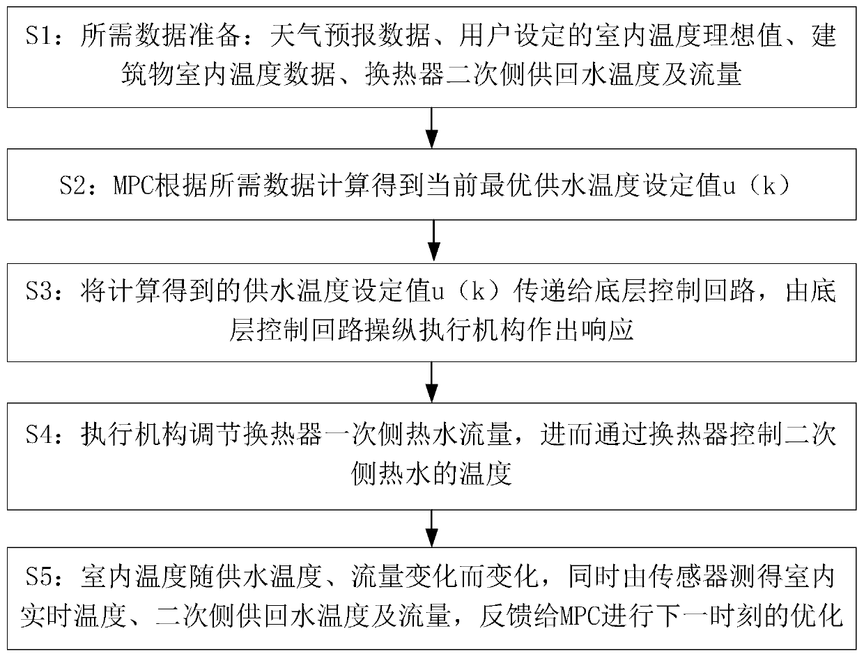
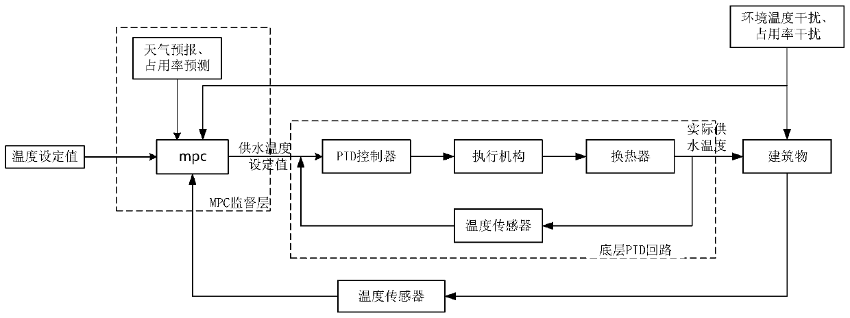
The invention discloses a building temperature control method and system based on model predictive control. Based on model predictive control (MPC), the method performs heat supply temperature adjustment, adds prediction of interference in predictive control, and compensates for upcoming ambient temperature changes. The system comprises: an MPC controller for maintaining the room temperature of abuilding at a determined most comfortable temperature value and calculating an optimal heat supply temperature value; a PID controller used for controlling an executing mechanism to respond accordingto the optimal heat supply temperature value and the secondary side water supply and return temperature; an executing mechanism for adjusting the primary side hot water flow of a heat exchanger and controlling the temperature of secondary side hot water through the heat exchanger; a first temperature sensor for collecting the temperature of the secondary side hot water of the heat exchanger and sends the temperature to the PID controller; and a second temperature sensor used for collecting the indoor real-time temperature of the building and sending the indoor real-time temperature to the MPCcontroller. According to the method and the system, the indoor temperature is more stable, the comfort level of a user is improved, and the heat supply energy consumption is remarkably reduced.

Description

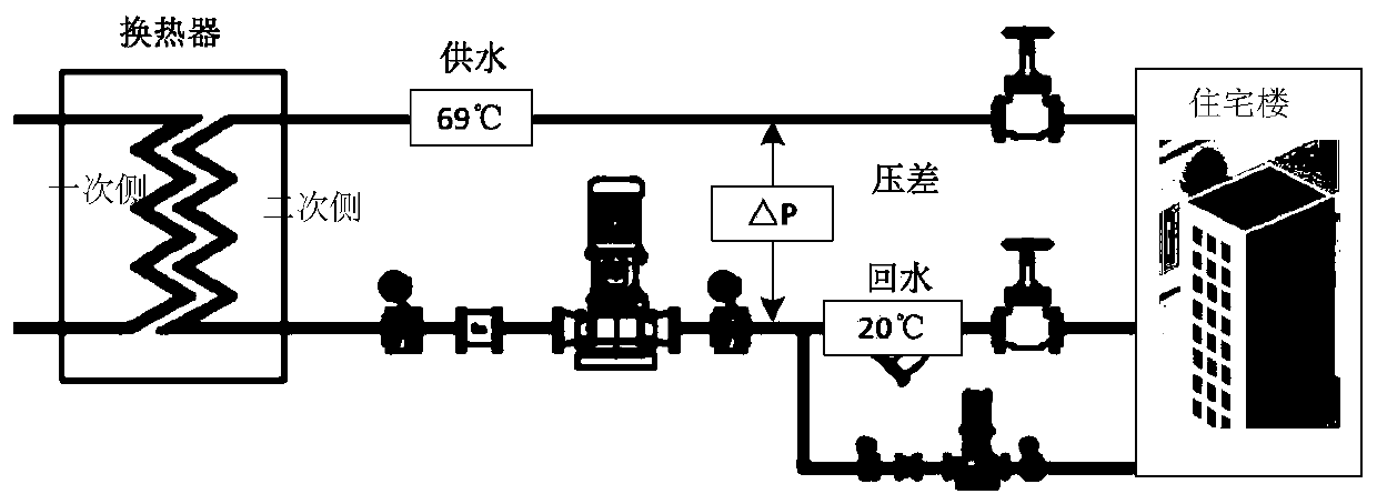
technical field [0001] The invention relates to a building temperature control method and system based on model predictive control, belonging to the technical field of heat supply control. Background technique [0002] Many countries have heating needs in winter, including heating design of residential buildings and non-residential buildings. In northern China, urban and some rural areas are dominated by central heating. The steam and hot water generated by the centralized heat source pass through the primary heat exchange station and the primary pipe network to the secondary heat exchange station, where heat exchange is performed in the secondary heat exchange station, and the heat is transferred to the secondary pipe network, and the heat passes through the secondary pipe network. The net is passed to the heat users at the grassroots level for production and life. Such as figure 1 As shown, the secondary heat exchange station is responsible for the concentration and exc...

Claims


Application Information

Patent Timeline
Patent Type & Authority Applications(China)
IPC IPC(8): F24D19/10
CPCF24D19/1009
Inventor 蒋萍鞠晨曦李实王孝红于宏亮黄冰
Owner UNIV OF JINAN
Learn More