Passive sensing circuit and control method thereof

A passive sensing and circuit technology, applied in the field of sensing, can solve the problems of large differences in sensing accuracy, unstable transmission power of readers, and inability to guarantee stability of continuous waves, so as to improve sensing accuracy and sensing distance. Effect

Pending Publication Date: 2020-03-17
ZHEJIANG JOHAR TECH CO LTD
View PDF8 Cites 0 Cited by
  • Summary
  • Abstract
  • Description
  • Claims
  • Application Information

AI Technical Summary

Problems solved by technology

This does two things against the sensor
The first point is that the continuous wave emitted by the reader will bring strong radio frequency interference. If the power consumption of the sensor is large, the power supply suppression of the sensor is poor, or the sensor is external, the radio frequency interference will be very large, which may make the entire sensor The accuracy varies greatly in different application scenarios; the second point is that the continuous wave received by the tag itself cannot guarantee stability, resulting in unstable power supply to the sensor. In some application scenarios, the tag, reader or other objects may be moving , the RF energy received by the tag will change, or the tag is affected by the RF signal of other readers, or the transmitting power of the reader is unstable after long-term operation, resulting in unstable power supply. Sensing accuracy and sensing distance of passive RFID tags with sensors

Method used


Image

  • Passive sensing circuit and control method thereof
  • Passive sensing circuit and control method thereof
  • Passive sensing circuit and control method thereof

Examples


Embodiment 1

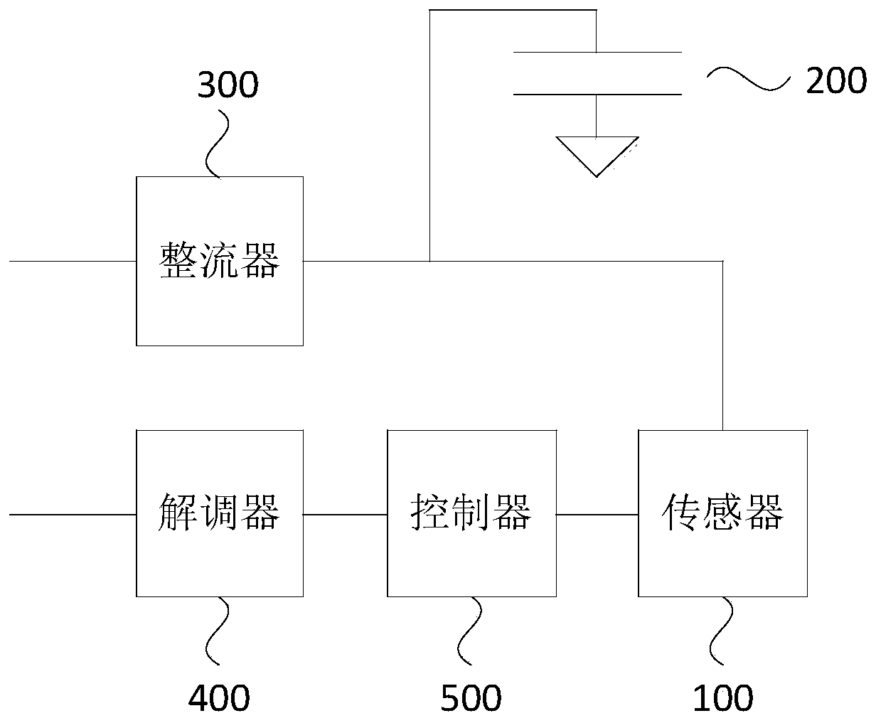
[0039] Such as figure 1 As shown, Embodiment 1 of the present invention provides a passive sensing circuit, which includes a sensor 100 , a first capacitor 200 , a rectifier 300 , a demodulator 400 and a controller 500 .

[0040] Specifically, the sensor 100 is used to generate sensing data according to the monitored object; the first capacitor 200 is used to provide the sensor 100 with a first working voltage; the rectifier 300 is used to convert the received induced voltage into a second working voltage to give The first capacitor 200 is charged; the demodulator 400 is used to analyze the first instruction contained in the induced voltage; the controller 500 is used to control the sensor 100 to start working according to the first instruction.

[0041] In this embodiment, the rectifier 300 is connected in series with the sensor 100 , and the first capacitor 200 is connected in parallel between the rectifier 300 and the sensor 100 . The rectifier 300 is a device that convert...

Embodiment 2

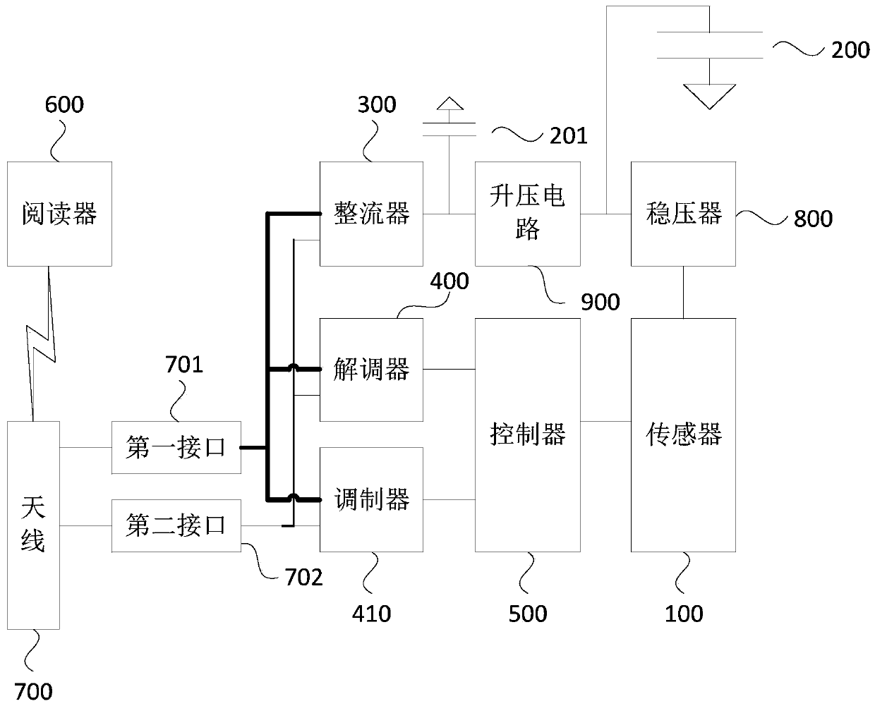
[0045] like figure 2 As shown, Embodiment 2 of the present invention provides a passive sensing circuit. Embodiment 2 of the present invention is further optimized on the basis of Embodiment 1 of the present invention. The passive sensing circuit includes a sensor 100, a first capacitor 200 , rectifier 300 , demodulator 400 , controller 500 , modulator 410 , reader 600 , antenna 700 , first interface 701 , second interface 702 , voltage regulator 800 , boost circuit 900 and second capacitor 201 .

[0046] Specifically, the sensor 100 is used to generate sensing data according to the sensing object; the first capacitor 200 is used to provide the sensor 100 with a first working voltage; the rectifier 300 is used to convert the received induced voltage into a second working voltage for Charge the first capacitor 200; the demodulator 400 is used to analyze the first instruction included in the induced voltage; the controller 500 is used to control the sensor 100 to start working ...

Embodiment 3

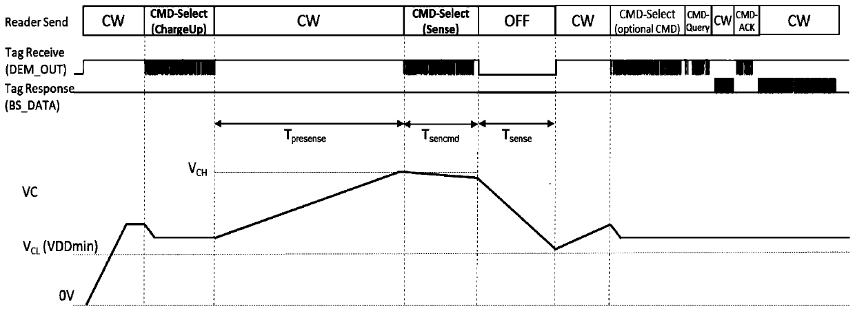
[0052] like Figure 5As shown, Embodiment 3 of the present invention provides a control method of a passive sensing circuit, and the control method of the passive sensing circuit includes:

[0053] S110. Control the reader to send a radio frequency signal to charge the first capacitor in the passive sensing circuit.

[0054] S120. Based on the first capacitor as a working power source, control the reader to send the radio frequency signal to control the reader to stop sending the radio frequency signal.

[0055] S130. Control the reader to send the radio frequency signal to receive the sensing data returned by the sensor.

[0056] In this embodiment, the passive sensing circuit can be set in the chip. When the sensor sensing data is needed, firstly control the reader to send a wireless radio frequency signal to start the passive sensing circuit, that is, control the reader to send a terminal time The continuous wave placed outside the chip will generate an induced voltage af...


PUM


Abstract

The embodiment of the invention discloses a passive sensing circuit and a control method thereof. The passive sensing circuit comprises a sensor used for sensing data; a first capacitor used for providing a first working voltage for the sensor; a rectifier used for converting the received induced voltage into a second working voltage so as to charge the first capacitor; a demodulator used for analyzing a first instruction included in the induced voltage; and a controller used for controlling the sensor to start to work according to the first instruction. According to the embodiment of the invention, the sensing precision and the sensing distance of a passive RFID label with the sensor are improved.

Description

technical field [0001] Embodiments of the present invention relate to sensing technology, in particular to a passive sensing circuit and a control method thereof. Background technique [0002] Radio Frequency Identification (RFID) is a kind of automatic identification technology. It uses radio frequency to perform non-contact two-way data communication, and uses radio frequency to read recording media (electronic tags or radio frequency cards). Writing, so as to achieve the purpose of identifying targets and data exchange, it is considered to be one of the most potential information technologies in the 21st century. [0003] However, for the existing passive RFID tag circuit with sensors, the reader always emits continuous waves to provide power to the tags and the sensors on them during the working process of the sensors. This does two things against the sensor. The first point is that the continuous wave emitted by the reader will bring strong radio frequency interferenc...

Claims


Application Information

Patent Timeline
Patent Type & Authority Applications(China)
IPC IPC(8): G06K19/07G06K19/077
CPCG06K19/07771G06K19/07749G06K19/0715
Inventor 易俊汤兴凡祝祺斌
Owner ZHEJIANG JOHAR TECH CO LTD
Why Eureka
Try Eureka