Scrap iron briquetting recycling equipment

A technology for recycling equipment and iron filings, applied in the direction of presses, manufacturing tools, etc., can solve the problems of low recycling efficiency, increased recycling cost, and high labor intensity, and achieve the effect of reducing recycling cost, improving recycling efficiency, and increasing transportation volume.

Active Publication Date: 2020-03-20
嘉兴众衡电气科技有限公司
View PDF5 Cites 2 Cited by
  • Summary
  • Abstract
  • Description
  • Claims
  • Application Information

AI Technical Summary

Problems solved by technology

[0002] Machining is still a very common production and processing method, but a large amount of long iron filings will be produced during the machining process. At present, the recycling method is to pack the fluffy and messy iron filings into blocks by hydraulic pressure or hot pressing. Steel mills return to the furnace, but due to the large volume of hydraulic and hot-pressing equipment, they cannot be moved at will, so the fluffy and messy iron filings must be transported in bulk to the recycling company and then pressed into blocks. It is inconvenient to use, because the fluffy and messy iron filings take up a lot of space, so the iron filings are easily scattered on the road during transportation, which seriously endangers road driving safety. At the same time, the labor intensity is high and the recycling efficiency is low, which increases the recycling cost. In some The area where machining enterprises are concentrated, this problem has become a social problem that plagues the people and the government

Method used


Image

  • Scrap iron briquetting recycling equipment
  • Scrap iron briquetting recycling equipment
  • Scrap iron briquetting recycling equipment

Examples


Embodiment Construction

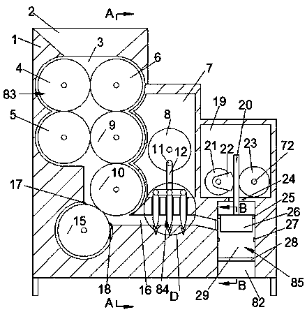
[0016] Combine below Figure 1-5 The present invention is described in detail, and for convenience of description, the orientations mentioned below are now stipulated as follows: figure 1 The up, down, left, right, front and back directions of the projection relationship itself are the same.

[0017] refer to Figure 1-5, according to an embodiment of the present invention, a kind of iron filings briquette recycling equipment includes a main body 1, a rolling chamber 3 is provided inside the main body 1, and a wall communicating with the outside world is provided on the upper side wall of the rolling chamber 3. The feed port 2, the right side of the rolling chamber 3 is provided with a rocker chamber 7, the right side of the rocker chamber 7 is provided with a briquetting drive chamber 19, and the lower side of the briquetting drive chamber 19 is provided with a weight chamber 29. The lower side of the rocker chamber is provided with a shear chamber 16 connecting the rolling...


PUM


Abstract

The invention discloses scrap iron briquetting recycling equipment. The equipment comprises a main body, a rolling cavity is formed in the main body, a feeding hole communicated with the outside is formed in the upper side wall of the rolling cavity, a rocker cavity is formed on right of the rolling cavity, a briquetting driving cavity is formed on right of the rocker cavity, a heavy hammer cavityis formed under the briquetting driving cavity, a shearing cavity communicated with the rolling cavity and the heavy hammer cavity is formed under the rocker cavity, a discharging hole communicated with the outside is formed in the lower side wall of the heavy hammer cavity, and a first transmission cavity is formed behind the rolling cavity. Scrap iron can be rolled for multiple times by rollersinto a plate shape, then cut into small pieces by a cutting blade, and finally briquetted by a heavy hammer, the processed scrap iron is convenient to transport, part of the transport amount can be increased, the labor force is reduced, the recycling cost is reduced, the recycling efficiency is improved, and the equipment can be popularized to different machining factories.

Description

technical field [0001] The invention relates to the technical field of iron scrap recycling, in particular to an iron scrap briquette recycling device. Background technique [0002] Machining is still a very common production and processing method, but a large amount of long iron filings will be produced during the machining process. At present, the recycling method is to pack the fluffy and messy iron filings into blocks by hydraulic pressure or hot pressing. Steel mills return to the furnace, but due to the large volume of hydraulic and hot-pressing equipment, they cannot be moved at will, so the fluffy and messy iron filings must be transported in bulk to the recycling company and then pressed into blocks. It is inconvenient to use, because the fluffy and messy iron filings take up a lot of space, so the iron filings are easily scattered on the road during transportation, which seriously endangers road driving safety. At the same time, the labor intensity is high and the ...

Claims


Application Information

Patent Timeline
Patent Type & Authority Applications(China)
IPC IPC(8): B30B9/32B30B15/00
CPCB30B9/32B30B9/326B30B9/327B30B15/0005
Inventor 不公告发明人
Owner 嘉兴众衡电气科技有限公司
Why Eureka
Try Eureka