Smelting furnace spray gun and smelting furnace

A smelting furnace and lance technology, applied in the field of smelting furnaces, can solve the problems that the pressure of the lance cannot be guaranteed, the process requirements cannot be adjusted for the lance, and the service life of the lance and the furnace is greatly affected, so as to avoid clogging, the adjustable range is large, and the service life is guaranteed. Effect

Pending Publication Date: 2020-03-20
CHINA ENFI ENGINEERING CORPORATION
0 Cites 1 Cited by

AI-Extracted Technical Summary

Problems solved by technology

[0002] Existing smelting furnaces such as side-blowing furnaces and oxygen-enriched electrothermal reduction furnaces all use spray guns. Among them, the spray gun can deliver fuel and combustion-supporting gas at the same time, but it can only be fine-tuned. A large amount of fuel and combustion-support...

Method used

According to a further embodiment of the first aspect of the present invention, the combustion-supporting gas seat 7 includes a combustion-supporting gas seat body 701 and a cover 702; the combustion-supporting gas seat body 701 defines a combustion-supporting gas inlet cavity 7011, and There is an opening communicating with the combustion-supporting gas inlet chamber 7011; the cover 702 is set on the opening and sealed and fixed with the combustion-supporting gas seat body 701, so that installation and maintenance can be facilitated.
According to an embodiment of the first aspect of the present invention, the outer diameter of the outer pipe end pipe 4 is the same as the outer diameter of the outer pipe 1 and the inner diameter of the outer pipe end pipe 4 is less than the inner diameter of the outer pipe 1, thus, The outer end tube 4 can be easily welded on the outer tube 1; the outer diameter of the inner tube end tube 3 is smaller than the inner diameter of the outer tube 1, so that the inner tube end tube 3 can rotate inside the outer tube 1; the inner tube end tube The inner diameter of 3 is the same as the inner diameter of the outer pipe end pipe 4, so that the dri...

Abstract

The invention discloses a smelting furnace spray gun and a smelting furnace. The smelting furnace spray gun comprises an outer pipe, an outer pipe end pipe, an inner pipe and an inner pipe end pipe. Awall body of the outer pipe end pipe is provided with a plurality of axially-penetrating outer pipe end air supply channels. The outer pipe end pipe and the outer pipe are coaxially arranged, and anouter ring portion of one end portion of the outer pipe end pipe is welded and fixed with one end portion of the outer pipe. The inner pipe is rotatably and coaxially arranged in the outer pipe, andan axial air supply channel with an annular section is arranged between an outer circumferential surface of the inner pipe and the inner circumferential surface of the outer pipe. The inner pipe end pipe is coaxially arranged in the outer pipe, and a plurality of axially-penetrating inner pipe end air supply channels are arranged on the wall body of the inner pipe end pipe. One end portion of theinner pipe end pipe is welded and fixed with one end portion of the inner pipe. And the other end portion of the inner pipe end pipe is propped against an inner ring portion of one end portion of theouter pipe end pipe. By using the smelting furnace spray gun, a combustion-supporting gas inlet amount and a fuel conveying amount can be adjusted, an adjusting range is large, and service lives of the smelting furnace spray gun and the smelting furnace are effectively guaranteed.

Application Domain

Technology Topic

Image

  • Smelting furnace spray gun and smelting furnace
  • Smelting furnace spray gun and smelting furnace

Examples

  • Experimental program(1)

Example Embodiment

[0040] The embodiments of the present invention are described in detail below. Examples of the embodiments are shown in the accompanying drawings, in which the same or similar reference numerals indicate the same or similar elements or elements with the same or similar functions. The embodiments described below with reference to the drawings are exemplary, and are only used to explain the present invention, but should not be understood as limiting the present invention.
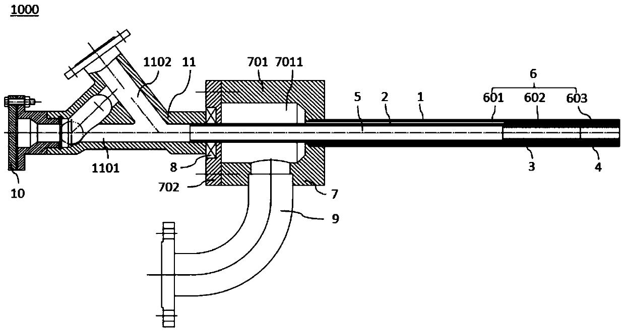
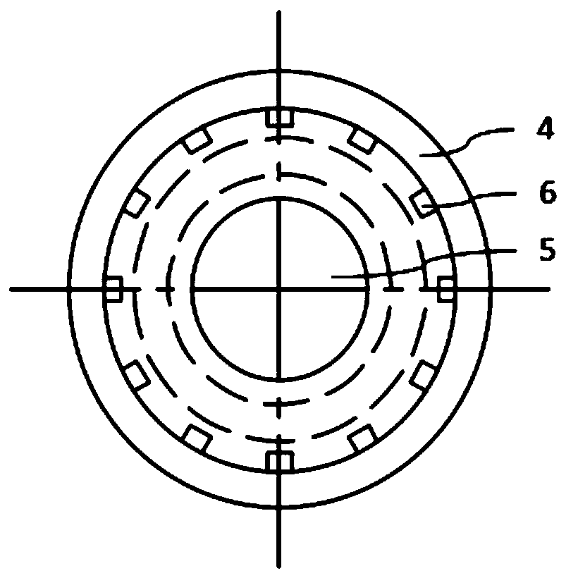
[0041] Combine below Figure 1 to Figure 2 A smelting furnace spray gun 1000 according to an embodiment of the first aspect of the present invention will be described.
[0042] Such as figure 1 with figure 2 As shown, the smelting furnace spray gun 1000 according to the embodiment of the first aspect of the present invention includes an outer tube 1, an outer tube end tube 4, an inner tube 2 and an inner tube end tube 3, and the wall of the outer tube end tube 4 A plurality of outer tube end air supply passages 603 are provided with axially penetrating through, the plurality of outer tube end air supply passages 603 are spaced along the circumferential direction; the outer tube end tube 4 and the outer tube 1 are arranged coaxially and the outer tube end The outer ring part of one end of the tube 4 is welded and fixed with one end of the outer tube 1; the multiple outer tube end air supply channels 603 are located in the lumen of the outer tube 1 on the radial projection plane; the inner tube 2 is rotatably the same The shaft is arranged in the outer tube 1, and an axial air supply channel 601 with an annular cross section is formed between the outer circumferential surface of the inner tube 2 and the inner circumferential surface of the outer tube 1. The inner tube end tube 3 is coaxially arranged in the outer tube 1, and The wall of the tube end tube 3 is provided with a plurality of inner tube end air supply channels 602 axially penetrating, and the plurality of inner tube end air supply channels 602 are spaced apart along the circumferential direction; the inner tube end tube 3 and the inner tube 2 Coaxially arranged and one end of the inner tube end tube 3 and one end of the inner tube 2 are welded and fixed, so that the inner tube end tube 3 and the inner tube 2 can be rotated synchronously, and a plurality of inner tube end gas channels 602 communicates with the axial air supply channel 601; the other end of the inner tube end tube 3 is pressed against the inner ring part of one end of the outer tube end tube 4, so that the lumen of the inner tube 2 and the inner tube end tube 3 The lumen and the lumen of the outer tube end tube 4 are sequentially connected to form the fuel delivery channel 5, while the axial air delivery channel 601, the inner tube end air delivery channel 602, and the outer tube end air delivery channel 603 are connected to form the combustion-supporting gas delivery channel 6 ; The inner tube 2 is rotated to adjust the degree of alignment between the air supply channel 602 at the end of the inner tube and the air supply channel 603 at the end of the outer tube.
[0043] According to the smelting furnace spray gun 1000 of the embodiment of the first aspect of the present invention, the working process is: when fuel and combustion-supporting gas need to be introduced into the smelting furnace, the fuel enters the inner tube 2 from the other end of the inner tube 2, and then passes through the inner tube in turn 2, the lumen of the inner tube end tube 3 and the outer tube end tube 4 enter the smelting furnace; the combustion-supporting gas passes through the axial air supply channel 601, the air supply channel 602 at the inner tube end and the outer tube end The combustion-supporting gas supply passage 6 formed by the partial air supply passage 603 is connected to enter the smelting furnace. When the demand for the gas delivery volume of the combustion-supporting gas is the largest, rotate the inner tube 2 so that the multiple inner pipe end air-feeding channels 602 and the multiple outer tube end air-feeding channels 603 are aligned exactly one to one. When it is necessary to reduce the delivery volume of the combustion-supporting gas Rotating the inner tube 2 makes the multiple inner tube end air supply channels 602 and the multiple outer tube end air supply channels 603 relatively staggered one by one, reducing the overlapping area of ​​the two alignments, thereby reducing the combustion-supporting gas supply channels 6 To achieve the effect of adjusting the amount of combustion-supporting gas delivery, when the combustion-supporting gas is not required to be transported, the inner tube 2 is rotated so that the multiple inner pipe end air passages 602 and the multiple outer pipe end air passages 603 are completely staggered, that is, The plurality of inner tube end air supply channels 602 and the plurality of outer tube end air supply channels 603 are not connected with each other; thus, the amount of combustion-supporting gas and fuel delivery amount delivered by the smelting furnace spray gun can be easily adjusted, which can ensure the reduction The gas delivery rate of the combustion-supporting gas is ensured at the same time to ensure the gas ejection speed, avoiding the blockage of the smelting furnace lance 1000, and ensuring the life of the smelting furnace lance 1000 and the melting furnace. In addition, the smelting furnace lance 1000 has a large adjustable range for the combustion-supporting gas delivery channel 6 Conducive to the smooth progress of process operations.
[0044] According to an embodiment of the first aspect of the present invention, the cross section of the air supply channel 602 at the end of the inner tube and the air supply channel 603 at the end of the outer tube are the same. As a result, the multiple inner tube end air supply passages 602 and the multiple outer tube end air supply passages 603 can be completely aligned in one-to-one correspondence. In this way, the combustion-supporting gas delivery passage 6 of the smelting furnace spray gun 1000 can be adjusted in a wide range and is easy to control. .
[0045] According to an embodiment of the first aspect of the present invention, the outer diameter of the outer tube end tube 4 is the same as the outer diameter of the outer tube 1, and the inner diameter of the outer tube end tube 4 is smaller than the inner diameter of the outer tube 1, whereby the outer end The tube 4 can be conveniently welded to the outer tube 1; the outer diameter of the inner tube end tube 3 is smaller than the inner diameter of the outer tube 1, so that the inner tube end tube 3 can rotate inside the outer tube 1; the inner diameter of the inner tube end tube 3 The inner diameter of the end tube 4 is the same as that of the outer tube, so that the drill can easily and reliably block the fuel delivery channel 5; the inner diameter of the inner tube end tube 3 and the inner diameter of the outer tube end tube 4 are both smaller than the inner diameter of the inner tube 2 In this way, the fuel speed increases after passing through the inner diameter of the inner tube end tube 3 and the outer tube end tube 4.
[0046] According to an embodiment of the first aspect of the present invention, it further includes a combustion-supporting gas seat 7. The combustion-supporting gas seat 7 is provided with a combustion-supporting gas inlet chamber 7011, and the combustion-supporting gas seat 7 is provided with a first combustion-supporting gas inlet chamber 7011. The mounting hole and the second mounting hole, the first mounting hole and the second mounting hole are coaxially arranged and distributed on both sides of the combustion-supporting gas seat 7; the other end of the outer tube 1 is fixed in the first mounting hole, thereby, the combustion-supporting gas It can enter the combustion-supporting gas delivery channel 6 through the combustion-supporting gas inlet cavity 7011; the other end of the inner pipe 2 passes through the first mounting hole, the combustion-supporting gas inlet cavity 7011 and the second mounting hole and is rotatably supported in the second mounting hole In this way, the combustion-supporting gas can be separated from the fuel.
[0047] According to a further embodiment of the first aspect of the present invention, the combustion-supporting gas holder 7 includes a combustion-supporting gas holder body 701 and a cover 702; the combustion-supporting gas holder body 701 defines a combustion-supporting gas inlet cavity 7011, and the combustion-supporting gas holder body 701 is provided with The opening through which the combustion-supporting gas inlet chamber 7011 communicates; the cover 702 is arranged at the opening and is sealed and fixed with the combustion-supporting gas seat body 701, so that installation and maintenance can be facilitated.
[0048] According to a further embodiment of the first aspect of the present invention, the first mounting hole is provided on the combustion-supporting gas seat body 701 and opposite to the opening, and the second mounting hole is provided on the cover 702. Thus, the installation of the inner tube 2 can be facilitated.
[0049] According to a further embodiment of the first aspect of the present invention, a rotating device 8 is installed in the second mounting hole, and the other end of the inner tube 2 is rotatably supported on the rotating device 8, so that the other end of the inner tube 2 can be rotated The inner tube 2 is rotated, and the inner tube end tube 3 can be driven to rotate synchronously.
[0050] According to some embodiments of the first aspect of the present invention, it further includes a combustion-supporting gas inlet pipe 9. One end of the combustion-supporting gas inlet pipe 9 is fixed on the combustion-supporting gas seat 7 and the cavity of the combustion-supporting gas inlet pipe 9 is in communication with the combustion-supporting gas inlet cavity 7011. In this way, the combustion-supporting gas can enter the combustion-supporting gas inlet cavity 7011 through the combustion-supporting gas inlet pipe 9.
[0051] According to an embodiment of the first aspect of the present invention, it further includes a connecting piece 11 and a head 10, the connecting piece 11 defines a first channel 1101 and a second channel 1102, wherein the other end of the inner tube 2 is installed in the first channel 1101 In one end of the second channel 1102, one end of the second channel 1102 intersects with the first channel 1101, and the head 10 is detachably sealed at the other end of the first channel 1101. It is understandable that when fuel needs to be delivered into the smelting furnace, the head 10 is sealed at the other end of the first channel 1101, and the fuel enters the connecting piece 11 from the other end of the second channel 1102, and then enters the fuel delivery channel 5. It is transported into the smelting furnace through the fuel delivery channel 5. When the fuel delivery to the smelting furnace is stopped, the head 10 is removed from the other end of the first channel 1101, and then the drill is transferred from the other end of the first channel 1101 Inserting into the first passage 1101 and the fuel delivery passage 5, thus, the first passage 1101 and the fuel delivery passage 5 can be sealed, the structure is simple, and the operation is convenient.
[0052] The second aspect of the present invention also provides a smelting furnace.
[0053] The smelting furnace according to the embodiment of the second aspect of the present invention includes the smelting furnace lance 1000 of any one of the first aspect of the present invention.
[0054] In the description of this specification, descriptions with reference to the terms "one embodiment", "some embodiments", "exemplary embodiments", "examples", "specific examples", or "some examples" etc. mean to incorporate the implementation The specific features, structures, materials or characteristics described by the examples or examples are included in at least one embodiment or example of the present invention. In this specification, the schematic representations of the above terms do not necessarily refer to the same embodiment or example. Moreover, the described specific features, structures, materials or characteristics may be combined in any one or more embodiments or examples in a suitable manner.
[0055] Although the embodiments of the present invention have been shown and described, those of ordinary skill in the art can understand that various changes, modifications, substitutions, and modifications can be made to these embodiments without departing from the principle and purpose of the present invention. The scope of the present invention is defined by the claims and their equivalents.

PUM

no PUM

Description & Claims & Application Information

We can also present the details of the Description, Claims and Application information to help users get a comprehensive understanding of the technical details of the patent, such as background art, summary of invention, brief description of drawings, description of embodiments, and other original content. On the other hand, users can also determine the specific scope of protection of the technology through the list of claims; as well as understand the changes in the life cycle of the technology with the presentation of the patent timeline. Login to view more.

Similar technology patents

Classification and recommendation of technical efficacy words

  • Reduce the cross-sectional area

Electromagnetic valve

Owner:浙江中宝自控元件有限公司

Catheter

Owner:MEDTRONIC PS MEDICAL

Switchgear spout design

ActiveUS20140185193A1Reduce the cross-sectional areaSmall widthNon-enclosed substationsSwitchgear arrangementsElectrical switchingEngineering
Owner:EATON INTELLIGENT POWER LIMITED
Why Eureka
Try Eureka