A film capacitor

A film capacitor, No. 1 technology, applied in the direction of detailed information of capacitors, variable capacitors, mechanical variable capacitors, etc., can solve problems such as the capacity of film capacitors that cannot be solved, and achieve the goal of improving heat dissipation, enhancing internal structure, and optimizing performance Effect

Active Publication Date: 2022-01-18
无锡万盛电子有限公司
View PDF6 Cites 0 Cited by
  • Summary
  • Abstract
  • Description
  • Claims
  • Application Information

AI Technical Summary

Problems solved by technology

[0004] This technical solution can absorb the heat generated by the capacitor during operation by filling the inside of the first cavity, the first radiating pipe, the second radiating pipe and the connecting pipe with cooling liquid, thereby avoiding the accumulation of heat. A radiating pipe, a second radiating pipe and connecting pipes can quickly dissipate the heat absorbed in the cooling liquid; but this technical solution still cannot solve the problem of reducing the capacity of the installed film capacitor on the existing circuit board. It is necessary to remove the original film capacitor and replace it with a film capacitor with a small capacity to achieve the goal, resulting in the limitation of this solution

Method used


Image

  • A film capacitor
  • A film capacitor
  • A film capacitor

Examples


Embodiment approach

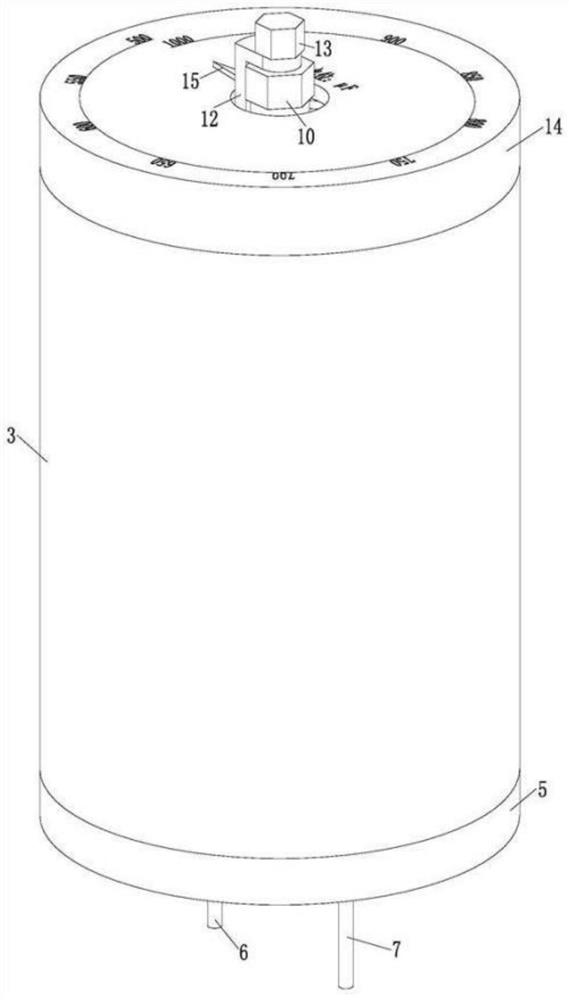
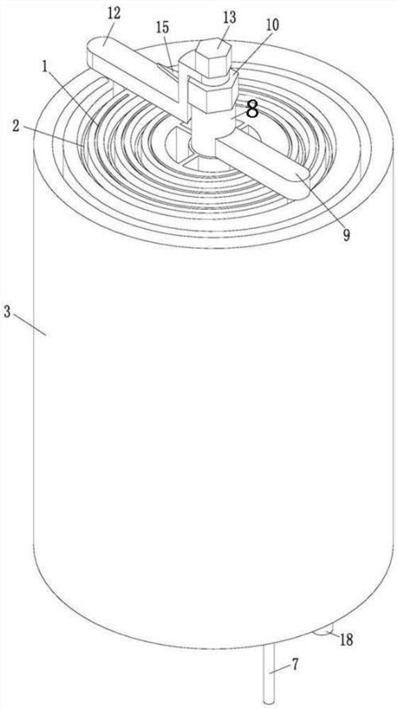
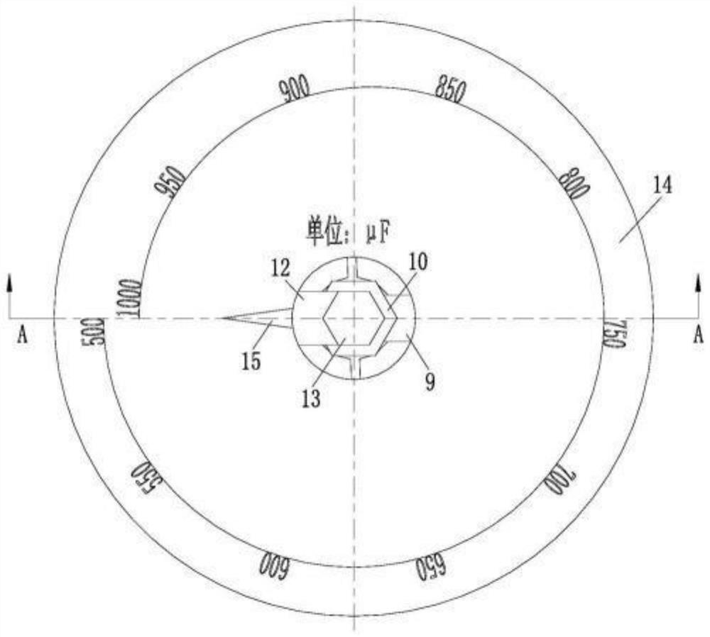
[0026] As an embodiment of the present invention, the center of the base body 3 is rotatably connected to the No. 1 rod 8, the upper part of the No. 1 rod 8 is fixedly connected with a No. 1 plate 9, and a No. 1 groove is arranged inside the No. 1 plate 9 , the inside of the No. 1 groove is slidingly connected to one of the guide rods 4, the upper end of the No. 1 rod 8 is welded with the No. 1 nut 10, and the inside of the No. 1 rod 8 is connected to the No. 2 rod 11 in rotation, so The top of the No. 2 rod 11 is fixedly connected with the No. 2 plate 12, and the inside of the No. 2 plate 12 is provided with a No. 2 groove, and the inside of the No. 2 groove is slidably connected with another guide rod 4. The upper end of the rod 11 is welded with the No. 2 nut 13; when working, if the staff pulls the guide rod 4 by hand to drive the No. 2 electrode foil to intersect with the horizontal plane in the direction of the force generated by the No. 2 through groove, it will cause th...


PUM


Abstract

The invention belongs to the technical field of electronic components, specifically a thin film capacitor, comprising a No. 1 electrode foil, a No. 2 electrode foil and a base body, the base body is cylindrical, and a No. 1 through groove is arranged in the base body. The No. 1 through-slot is a vortex line structure, and the No. 1 electrode foil is embedded in the No. 1 through-slot; the base body is also provided with a No. 2 through-slot, and the slot width of the No. 2 through-slot is equal to that of the No. 1 through-slot. Three times the width of the slot, the No. 2 slot is also a vortex structure, the No. 1 slot and the No. 2 slot are nested to form a double-swirl shape, and the base is made of polystyrene No. 2 electrode foil is arranged in the No. 2 through slot; the invention rotates the No. 2 electrode foil along the No. 2 slot, thereby reducing the overlapping area of ​​the No. 1 electrode foil and the No. 2 electrode foil projection, so that the staff The capacity of the film capacitor to store charge can be adjusted without disassembly, thereby improving the work efficiency of workers.

Description

technical field [0001] The invention belongs to the technical field of electronic components, in particular to a film capacitor. Background technique [0002] With the rapid development of electronic information technology, the upgrading speed of digital electronic products is getting faster and faster. The production and sales of consumer electronic products, mainly flat-panel TVs (LCD and PDP), notebook computers, digital cameras and other products, continue to grow. Capacitor industry growth. Capacitors, usually referred to as capacitance for their ability to hold charges, are denoted by the letter C. A capacitor, as the name suggests, is a "container for charging electricity", a device that holds charges. Capacitors are one of the electronic components widely used in electronic equipment, and are widely used in DC blocking, coupling, bypass, filtering, tuning loops, energy conversion, control, etc. in circuits. In addition, any two conductors (including wires) that ar...

Claims


Application Information

Patent Timeline
Patent Type & Authority Patents(China)
IPC IPC(8): H01G5/12H01G5/01H01G5/014
CPCH01G5/12H01G5/01H01G5/014
Inventor 张斌王浩
Owner 无锡万盛电子有限公司
Why Eureka
Try Eureka