
Automatic production device for brake disc housing

A technology for production devices and brake discs, which is applied to feed devices, positioning devices, storage devices, etc., can solve the problems of large equipment occupation, difficult turnover, unstable products, etc., and achieves small equipment occupation space, convenient storage and transportation, The effect of convenient automatic collection

Inactive Publication Date: 2020-03-24
河北华曙新能源汽车科技有限公司
View PDF7 Cites 2 Cited by
  • Summary
  • Abstract
  • Description
  • Claims
  • Application Information

AI Technical Summary

Problems solved by technology

[0002] In the production of brake discs, the main processing process of the product is produced by a single-process mold, which is divided into five sequences: blanking, stretching, trimming, flanging, and punching. There are 10 processes and 10 sets of equipment for the left and right parts; 10 processes Process machine, each process of the product needs turnover, production + turnover requires nearly 20 people, the efficiency is low, the average production is 150 sets per hour, and the number of waiting products is large, the on-site storage space is large, the summer production is easy to rust, and the cost is very high high
[0003] The material of the product is Q195-GP700, the 1.0mm thick material is very soft, the automatic feeding mold needs to be 3 meters long, and the mold cannot be sent out smoothly
[0004] As a result, there are problems such as many processes, high manual operation costs, unstable products, low production efficiency, difficult turnover, and large equipment occupation; therefore, it is necessary to improve the product processing technology and change it to automated production to reduce production costs.

Method used


Image

  • Automatic production device for brake disc housing
  • Automatic production device for brake disc housing
  • Automatic production device for brake disc housing

Examples


specific Embodiment approach 1

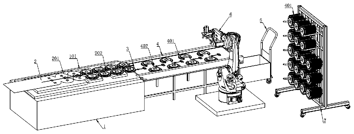
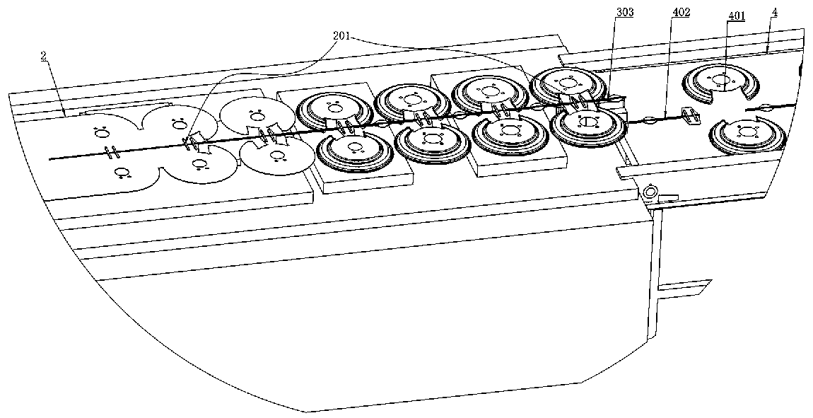
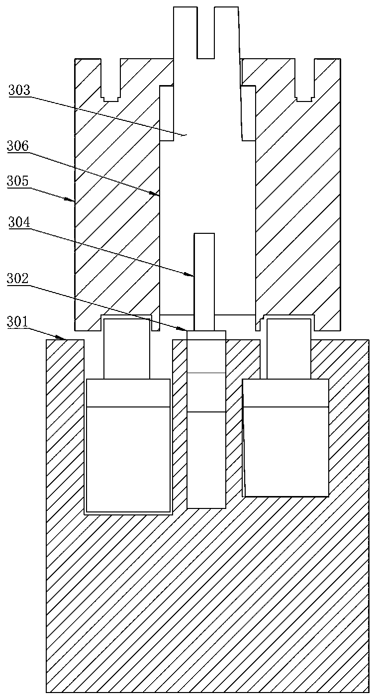
[0030] Specific implementation mode one: combine Figure 1-6 As shown, the brake disc cover automatic production device is characterized in that it includes a punching machine 1, a steel plate 2, a double floating material device 3, a conveyor belt 4, a waste trolley 5, a multi-axis joint handling robot 6 and a storage rack 7; The punching machine 1 is provided with a punching platform 101; the steel plate 2 is set on the punching platform 101; the right side of the steel plate 2 is provided with a material belt 201 on the punching platform 101; the double floating material device 3 is set on the punching platform 101 above the right end; the conveyor belt 4 is set on the right side of the bottom of the double floating material device 3; the waste trolley 5 is set under the right end of the conveyor belt 4; the multi-axis joint handling robot 6 is set on the side of the conveyor belt 4 The storage rack 7 is set on the right side of the multi-axis joint handling robot 6; the pu...


PUM


Abstract

The invention belongs to the technical field of brake disc production and relates to an automatic production device for a brake disc housing. According to the device, a 630T punching machine and die-combined continuous production is adopted to replace traditional single-procedure die production, and therefore, the repeated transfer machining of a workpiece is not needed, and production efficiencyis high; the workpiece is packed and warehoused directly after the workpiece is unloaded from a production line, and therefore, no products to be produced exists on a site, and the products are free of rusting; a middle reinforcement and bridging process is adopted to enhance the deformation strength of a material, so that the material is stably sent out of a mold, and therefore, automatic production is achieved; due to the design of a double-floating-material device, a punched and sheared brake disc and broken rib scraps can be effectively separated, and therefore, subsequent automatic collection of finished products can be facilitated; and the design of the whole device adopts automatic assembly line type production, and therefore, equipment just occupies small space, high production efficiency can be improved, and labor force can be greatly reduced.

Description

technical field [0001] The invention relates to the technical field of brake disc production, in particular to an automatic production device for brake disc casings. Background technique [0002] In the production of brake discs, the main processing process of the product is produced by a single-process mold, which is divided into five sequences: blanking, stretching, trimming, flanging, and punching. There are 10 processes and 10 sets of equipment for the left and right parts; 10 processes Process machine, each process of the product needs turnover, production + turnover requires nearly 20 people, the efficiency is low, the average production is 150 sets per hour, and the number of waiting products is large, the on-site storage space is large, the summer production is easy to rust, and the cost is very high high. [0003] The material of the product is Q195-GP700, and the 1.0mm thick material is very soft. The automatic feeding mold needs to be 3 meters long, and the mold ...

Claims


Application Information

Patent Timeline
Patent Type & Authority Applications(China)
IPC IPC(8): B21D28/02B21D43/12B21D43/18B21D43/20
CPCB21D28/02B21D43/12B21D43/18B21D43/20
Inventor 齐伟超郜云峰张建勋
Owner 河北华曙新能源汽车科技有限公司
Learn More