Stamping die waste discharging mechanism and stamping die thereof

A stamping die and discharge mechanism technology, applied in the field of stamping manufacturing, can solve the problems of being stuck on the mold, inconvenient operation, and restricting stamping production efficiency, and achieve the effect of avoiding adhesion, avoiding damage, and facilitating the transportation process

Active Publication Date: 2020-03-24
昆山日腾精密模具科技有限公司
View PDF5 Cites 0 Cited by
  • Summary
  • Abstract
  • Description
  • Claims
  • Application Information

AI Technical Summary

Problems solved by technology

[0002] With the rapid development of modern manufacturing industry, the manual feeding of stamping production has been gradually replaced by the automatic feeding mechanism. However, the large amount of waste generated by the stamping die during the production process has not been effectively discharged automatically, and the waste needs to be manually discharged after the machine is shut down. , so waste cleaning has always troubled and restricted the efficiency of stamping production, and because the stamping machine exerts a large impact on the profile to achieve stamping, then the stamped waste will be stuck on the mold, so manual operation is not easy to operate

Method used


Image

  • Stamping die waste discharging mechanism and stamping die thereof
  • Stamping die waste discharging mechanism and stamping die thereof
  • Stamping die waste discharging mechanism and stamping die thereof

Examples


Embodiment

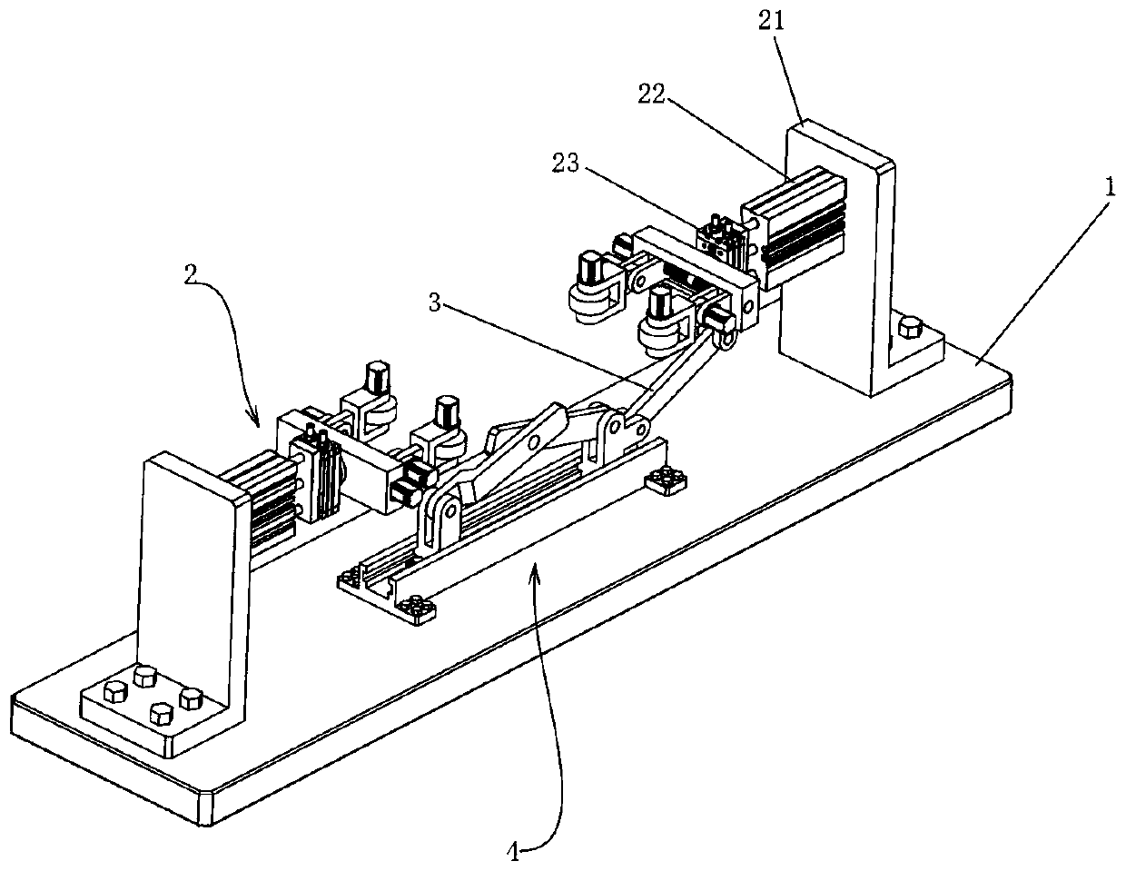
[0022] see Figure 1 to Figure 3 , the present invention provides a technical solution:

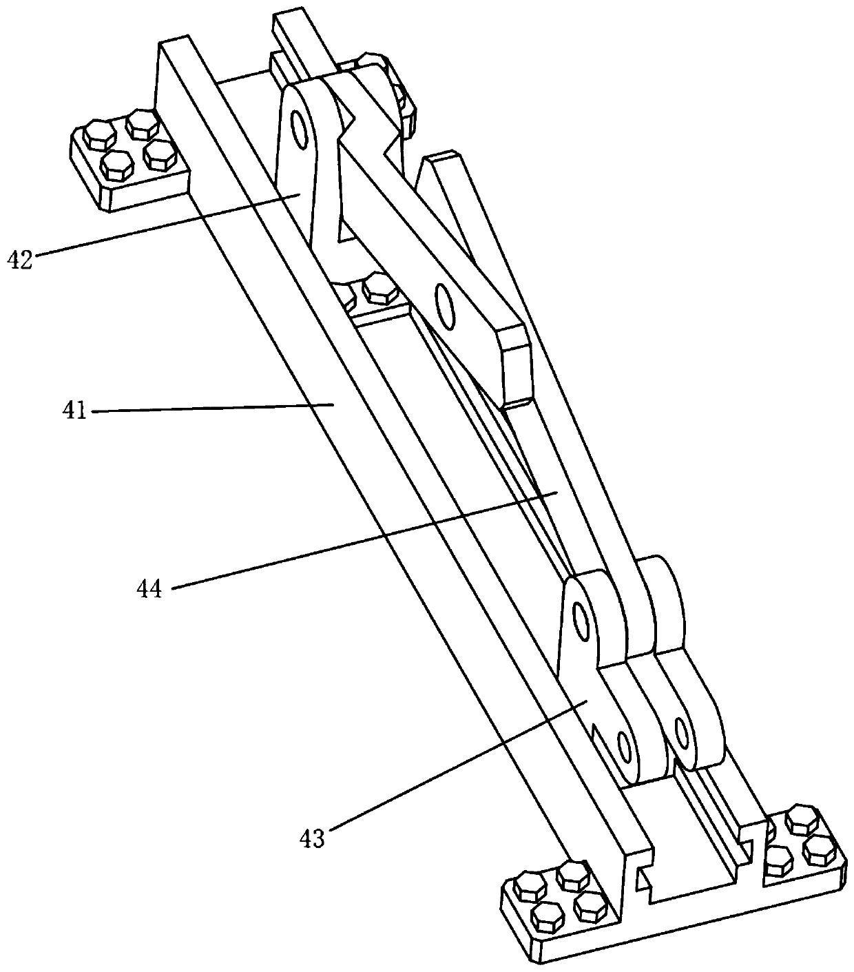
[0023] A stamping die waste material discharge mechanism, including a bottom plate 1, a conveying mechanism 2, a connecting rod 3 and a lifting mechanism 4, wherein:

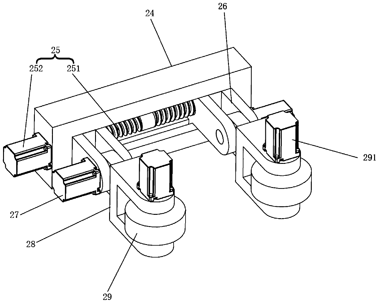
[0024] The two conveying mechanisms 2 are oppositely arranged, and the conveying mechanism 2 includes a support frame 21, a biaxial cylinder 22, a rotary cylinder 23, a mounting frame 24, a linear drive mechanism 25, a slider I 26, a steering gear 27, a roller mounting frame 28, a roller 29 and The motor I291, the support frame 21 is fixedly installed on the base plate 1 by bolts, the double-axis cylinder 22 is fixedly installed on the support frame 21 by bolts, the power output end of the double-axis cylinder 22 is fixed with a rotary cylinder 23 by bolts, and the installation frame 24 passes Bolts are fixedly installed on the power output end of the rotary cylinder 23, so the mounting frame 24 can rotate under the drive ...


PUM


Abstract

The invention provides a stamping die waste discharging mechanism and a stamping die thereof. The stamping die waste discharging mechanism comprises a bottom plate, conveying mechanisms, connecting rods and a lifting mechanism, wherein double-shaft air cylinders in the conveying mechanisms are mounted on the bottom plate through supporting frames, and rotating air cylinders are arranged at the power output ends of the double-shaft air cylinders; mounting frames are mounted at the power output ends of the rotating air cylinders; two sliding blocks I are movably mounted in each mounting frame; roller mounting frames are rotationally mounted at the ends of the sliding blocks I; rollers are rotationally mounted on the roller mounting frames; the lifting mechanism is positioned in the middle ofthe arranged conveying mechanisms; and the double-shaft air cylinder in one conveying mechanism is hinged to a movable assembly in the lifting mechanism through the corresponding connecting rod. Therollers make contact with the side edge of waste, and accordingly the conveying effect is achieved; through rotational mounting of the mounting frames and rotational mounting of the roller mounting frames, the rollers can be attached to the upper end face of the waste, and accordingly conveying of the waste different in thickness is achieved; and the lifting mechanism can jack up the waste, and adhesion between the waste and the die is avoided.

Description

technical field [0001] The invention relates to the technical field of stamping manufacturing, in particular to a waste material discharging mechanism of a stamping die and a stamping die thereof. Background technique [0002] With the rapid development of modern manufacturing industry, the manual feeding of stamping production has been gradually replaced by the automatic feeding mechanism. However, the large amount of waste generated by the stamping die during the production process has not been effectively discharged automatically, and the waste needs to be manually discharged after the machine is shut down. , so waste cleaning has always troubled and restricted the efficiency of stamping production, and because the stamping machine exerts a large impact on the profile to achieve stamping, the stamped waste will be stuck on the mold, so manual operation is not easy to operate. Contents of the invention [0003] The object of the present invention is to provide a stamping...

Claims


Application Information

Patent Timeline
Patent Type & Authority Applications(China)
IPC IPC(8): B21D45/04
CPCB21D45/04
Inventor 王卫民王熹
Owner 昆山日腾精密模具科技有限公司
Why Eureka
Try Eureka