Automatic copper pipe capping machine

A capping machine and copper tube technology, which is applied in the field of automatic copper tube capping machines, can solve problems such as low process efficiency, and achieve the effects of improving the success rate, reducing the difficulty of capping, and realizing the difficulty of capping.

Pending Publication Date: 2021-06-11
CHONGQING LONGYU PRECISION COPPER TUBE CO LTD
View PDF10 Cites 0 Cited by
  • Summary
  • Abstract
  • Description
  • Claims
  • Application Information

AI Technical Summary

Problems solved by technology

[0004] The purpose of the present invention is to provide an automatic copper pipe capping machine to solve the technical problem of low efficiency in the process of pipe fitting transportation and capping

Method used


Image

  • Automatic copper pipe capping machine
  • Automatic copper pipe capping machine

Examples


Embodiment Construction

[0027] The following is further described in detail through specific implementation methods:

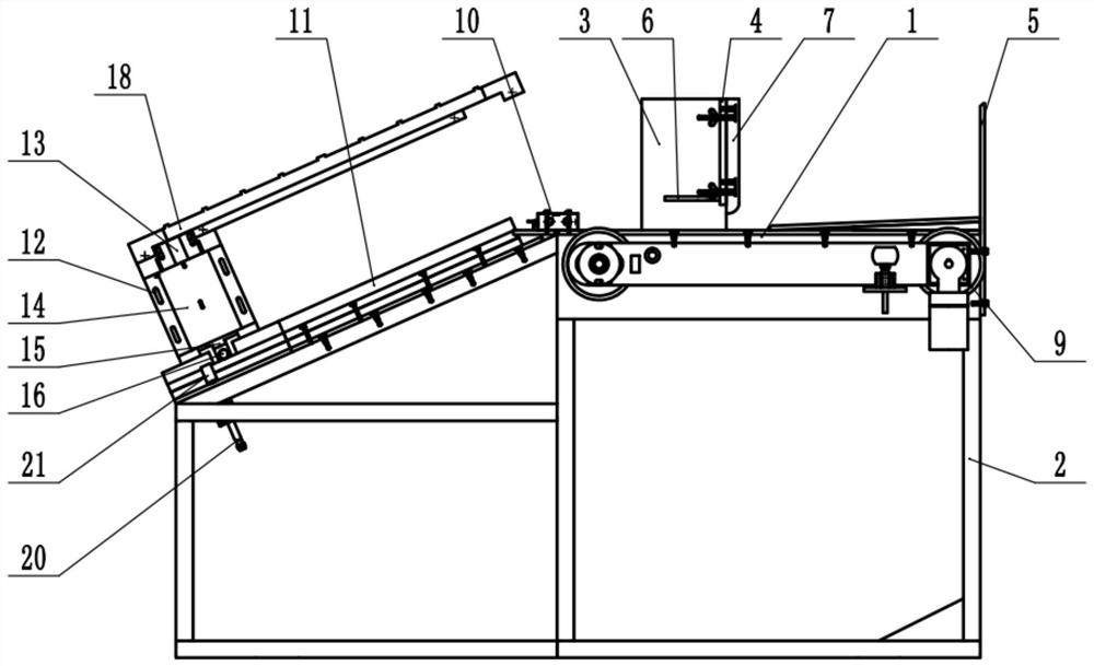
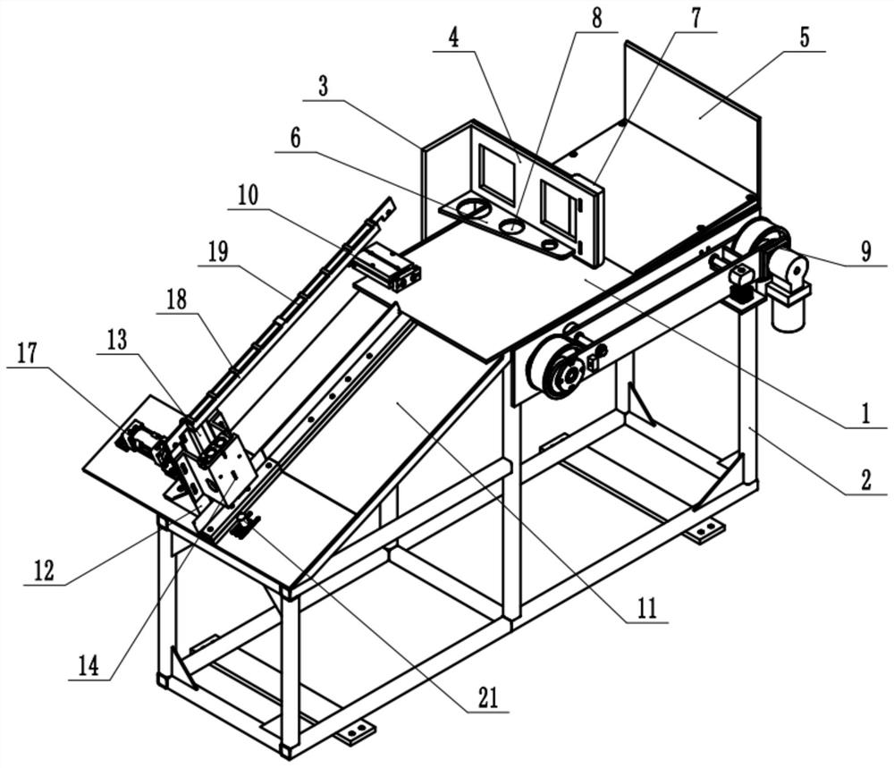
[0028] The reference signs in the drawings of the description include: feeding table 1, outrigger 2, movable plate 3, limit plate 4, baffle plate 5, reinforcing rib 6, buffer pad 7, through hole 8, conveyor belt 9, first telescopic Cylinder 10, guide plate 11, feeding seat 12, guide groove 13, second telescopic cylinder 14, first compression head 15, sliding hole 16, third telescopic cylinder 17, feeding frame 18, storage groove 19, first Drive motor 20, blocking block 21.

[0029] The embodiment is basically as attached figure 1 with attached figure 2 Shown: Automatic copper tube capping machine, including the limit mechanism and the cap blocking mechanism. The limit mechanism includes a feeding platform 1, the top of the feeding platform 1 is a plane, and the bottom of the feeding platform 1 is welded and fixed with a leg 2. The sidewall screw thread of feeding platform 1 is f...


PUM


Abstract

The invention relates to the technical field of pipe capping, and particularly discloses an automatic copper pipe capping machine which comprises a conveying table, the side wall of the conveying table is fixedly connected with a conveying belt, the top end of the conveying belt is not lower than the top face of the conveying table, the conveying table is vertically and slidably connected with a movable plate, the side wall of the movable plate is fixedly connected with a limiting plate, and the limiting plate is located over the conveying table. The invention aims to provide the automatic copper pipe capping machine so as to solve the technical problem that the efficiency is low in the pipe conveying and capping process.

Description

technical field [0001] The invention relates to the technical field of capping pipe fittings, and specifically discloses an automatic copper pipe capping machine. Background technique [0002] Steel pipes are widely used in some building components and pipelines. Among them, when the steel pipe is transported and stored, air, water, dust and other pollution factors often enter the interior of the pipe fittings, resulting in pollution of the steel pipe. Companies usually use caps to seal off both ends of the fittings. [0003] At present, in the traditional production process, the pipe caps are usually manually installed on both ends of the steel pipe by manpower. However, this method not only has low production efficiency, but also tends to cause the problem of falling off due to the loose caps fixed by the pipe fittings. occur. Contents of the invention [0004] The purpose of the present invention is to provide an automatic copper pipe capping machine to solve the tec...

Claims


Application Information

Patent Timeline
IPC IPC(8): B65B17/00B65B35/44B65G47/28B65G47/88
CPCB65B17/00B65B35/44B65G47/28B65G47/8823
Inventor 范新喜张海平沈才智张旭辉李玉林张杨俊
Owner CHONGQING LONGYU PRECISION COPPER TUBE CO LTD
Why Eureka
Try Eureka