Snap gauge structure in electric hydraulic tool and machining method and assembly-disassembly method thereof

A technology of hydraulic tools and clamping dies, which is applied in the field of clamping die structures, processing methods and loading and unloading, and can solve problems such as troublesome replacement of clamping die structures, many steps, and generation of metal debris

Pending Publication Date: 2020-03-24
台州奇峰工具有限公司
View PDF0 Cites 0 Cited by
  • Summary
  • Abstract
  • Description
  • Claims
  • Application Information

AI Technical Summary

Problems solved by technology

[0007] The object of the present invention is to solve the above-mentioned problems in the prior art, and provide the clamping structure and its processing method and loading and unloading method in the electro-hydraulic tool, wherein, the clamping structure and its loading and unloading method in the electro-hydraulic tool are convenient for clamping The replacement of the head, the loading and unloading process does not affect the smoothness of the movement of the parts, which solves the troublesome replacement of the existing clamping structure, and the problems of metal debris generated during the loading and unloading process; among them, the processing method of the clamping structure in the electro-hydraulic tool makes the clamping structure It is convenient to process, saves man-hours, and solves the problems of cumbersome processing and many steps in the existing clamping structure.

Method used


Image

  • Snap gauge structure in electric hydraulic tool and machining method and assembly-disassembly method thereof
  • Snap gauge structure in electric hydraulic tool and machining method and assembly-disassembly method thereof
  • Snap gauge structure in electric hydraulic tool and machining method and assembly-disassembly method thereof

Examples


Embodiment 1

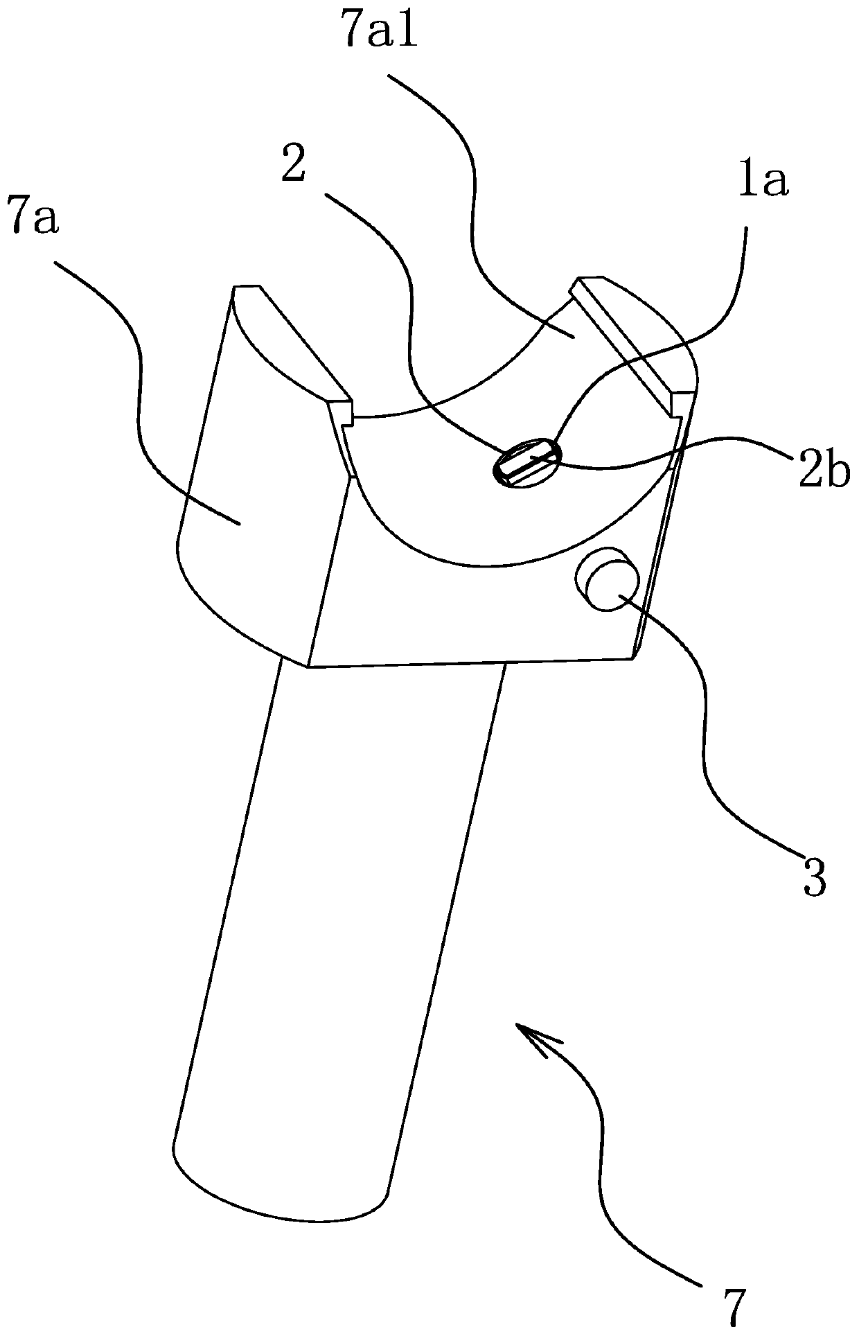
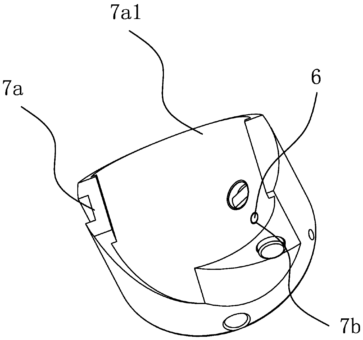
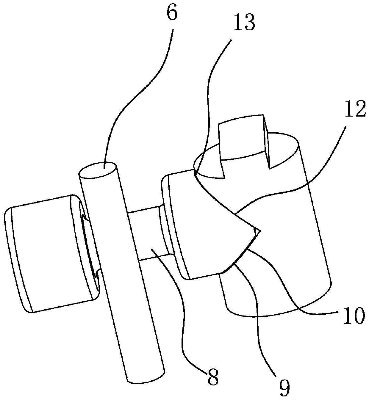
[0090] Such as Figure 1 to Figure 7 As shown, the clamping structure in the electric hydraulic tool includes a mounting hole 1, the mounting hole 1 has a first hole end 1a and a second hole end 1b, the clamping structure also includes a clamping head 2, and the clamping head 2 is located at the first The hole end 1a is provided with a through hole 2a on the card die head 2; it also includes a pressing shaft 3, which penetrates from the second hole end 1b, and the inner end of the pressing shaft 3 has an extension that can extend into or out of the through hole 2a. Into the section 3a, one end of the inserted section 3a has a stopper 3b that goes out of the perforation 2a, when the pressing shaft 3 is pressed inward, the clamping die head 2 enters the inner direction of the first hole end 1a and the clamping die head 2 has a tendency to reset ; The card die head 2 has a first state position 4 and a second state position 5. When the card die head 2 is in the first state positio...

Embodiment 2

[0103] Such as Figure 8 As shown, the difference between the present embodiment and the first embodiment is that the clamping die head 2 is in the shape of a rectangular block as a whole, the perforation 2a is a square hole and runs through the outer wall of the clamping die head 2, and the inner end of the pressing shaft 3 also has an extrusion with a slope. On the pressing surface 2, one end of the perforation 2a has an extrusion edge 2a2, and the extrusion surface 2 is an inclined plane. Extrusion surface 2 and extrusion surface 1 3c do not coexist, which is an independent technical feature in different technical solutions. In this technical solution, the rectangular block structure of the clamping die head 2 does not affect its up and down movement, and the extrusion surface is still used. The "point surface contact" or "edge surface contact" effect of the second and the extrusion edge 2a2 realizes the rapid downward pressure and rebound of the clamping die head 2. In pra...


PUM


Abstract

The invention provides a snap gauge structure in an electric hydraulic tool and belongs to the field of electric tools. The snap gauge structure comprises an installation hole provided with a first hole end and a second hole end. The snap gauge structure further comprises a snap gauge head and a pressing shaft. The snap gauge head is located at the first hole end. A through penetrating hole is formed in the snap gauge head. The pressing shaft penetrates in from the second hole end. The inner end of the pressing shaft is provided with a stretching-in section capable of stretching into or penetrating out of the penetrating hole. One end of the stretching-in section is provided with a blocking head penetrating out of the penetrating hole. When the pressing shaft is pressed inwards, the snap gauge head goes in toward the inside direction of the first hole end and has a reset trend. The snap gauge head has a first state position and a second state position. When the snap gauge head is in the first state position, the axial motion of the pressing shaft is limited; and when the snap gauge head is in the second state position, the blocking head and the stretching-in section can penetrate out of the penetrating hole. The problems that an existing snap gauge structure is troublesome to replace, and metal debris is produced in the assembly-disassembly process are solved.

Description

technical field [0001] The invention belongs to the field of electric tools, and relates to a clamping die structure in an electric hydraulic tool, a processing method and a loading and unloading method thereof. Background technique [0002] In the field of electro-hydraulic tools, the clamping structure is an indispensable structure. The clamping structure includes a clamping head and a pressing shaft. The function of the clamping structure is to clamp the mold base. The current clamping structure is a pin-type locking structure. Realizing the axial limit of the pressing shaft has many problems in practice, as follows: [0003] Taking electro-hydraulic pliers as an example, if the application number is 2019302031027, the name is the appearance design patent of electro-hydraulic pliers, hereinafter referred to as D1, and if the application number is 2018304939037, the name is the appearance design of hydraulic pliers, hereinafter referred to as D2, such as the stereogram of ...

Claims


Application Information

Patent Timeline
IPC IPC(8): B25F5/00
CPCB25F5/00
Inventor 陈雪峰
Owner 台州奇峰工具有限公司
Why Eureka
Try Eureka