Bead stringing finishing equipment for ornament processing

A beading and jewelry technology, which is applied in the field of beading and sorting equipment, can solve the problems of difficult fast packaging and easy beading collection and sorting, and achieve the effect of reducing the burden

Active Publication Date: 2020-03-24
肖松圣
View PDF6 Cites 0 Cited by
  • Summary
  • Abstract
  • Description
  • Claims
  • Application Information

AI Technical Summary

Problems solved by technology

[0005] In order to overcome the disadvantages that the beads cannot be easily collected and arranged, and it is difficult to pack the beads quickly, the technical problem of the present invention is to provide a beading sorting device for jewelry processing that can easily collect and organize the beads and facilitate the rapid packaging of the beads

Method used


Image

  • Bead stringing finishing equipment for ornament processing
  • Bead stringing finishing equipment for ornament processing
  • Bead stringing finishing equipment for ornament processing

Examples


Embodiment 1

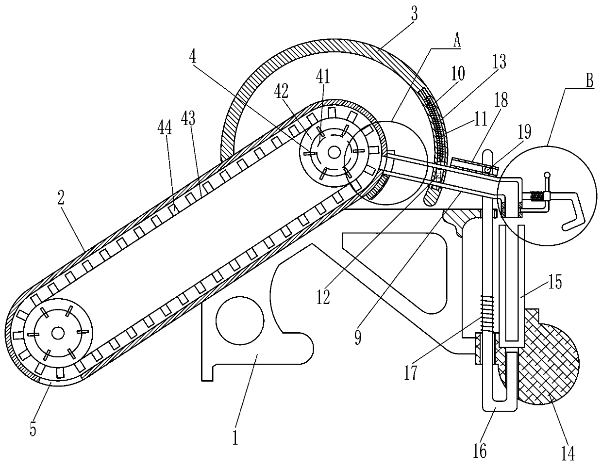
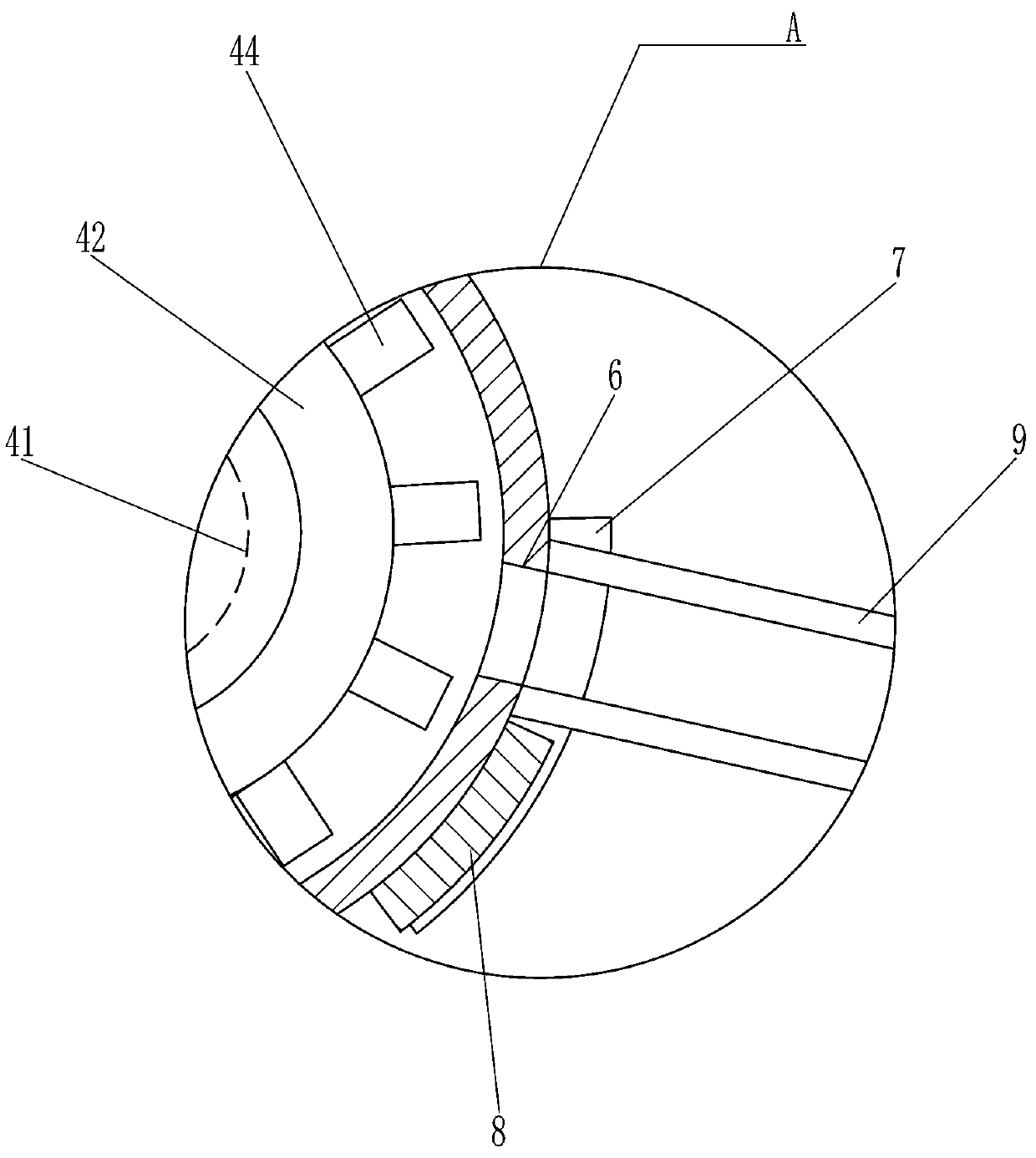
[0019] A kind of beading finishing equipment for jewelry processing, such as Figure 1-2 As shown, it includes a mounting seat 1, a transmission frame 2, an arc-shaped support rod 3, a conveying device 4, a fan-shaped disc 7, an arc-shaped baffle 8, a feeding tube 9, an arc-shaped sliding rod 11, an arc-shaped block 12, a first Compression spring 13, mounting block 14 and collecting frame 15, one side of mounting base 1 is provided with transmission frame 2, and the top of transmission frame 2 is provided with arc support bar 3, and transmission frame 2 is provided with conveying device 4, and transmission frame 2 bottom is opened There is a feed port 5, the upper part of the transmission frame 2 is provided with a discharge port 6, and the upper part of the rear side of the transmission frame 2 is rotatably connected with a fan-shaped disc 7. The fan-shaped disc 7 is provided with an arc-shaped baffle plate 8, and the arc-shaped support rod 3 is opened. There is an arc-shaped...

Embodiment 2

[0023] On the basis of Example 1, such as figure 1 with image 3 As shown, it also includes an L-shaped rod 16, a second compression spring 17, a guide frame 18, a protruding rod 19 and a handle 20, and the mounting base 1 is slidably connected with an L-shaped rod 16, and the L-shaped rod 16 is connected to the mounting base 1 The second compression spring 17 is connected between them, the top of the feed pipe 9 is provided with a guide frame 18, the upper front side of the L-shaped bar 16 is provided with a protruding rod 19, the protruding rod 19 is slidably matched with the guide frame 18, and the right side of the feed pipe 9 is provided with a There are 20 turning handles.

[0024] When the feed pipe 9 rotates counterclockwise, the feed pipe 9 drives the guide frame 18 to rotate counterclockwise. Through the cooperation of the guide frame 18 and the protruding rod 19, the L-shaped rod 16 moves upward, and the second compression spring 17 is stretched, and the L-shaped ...

Embodiment 3

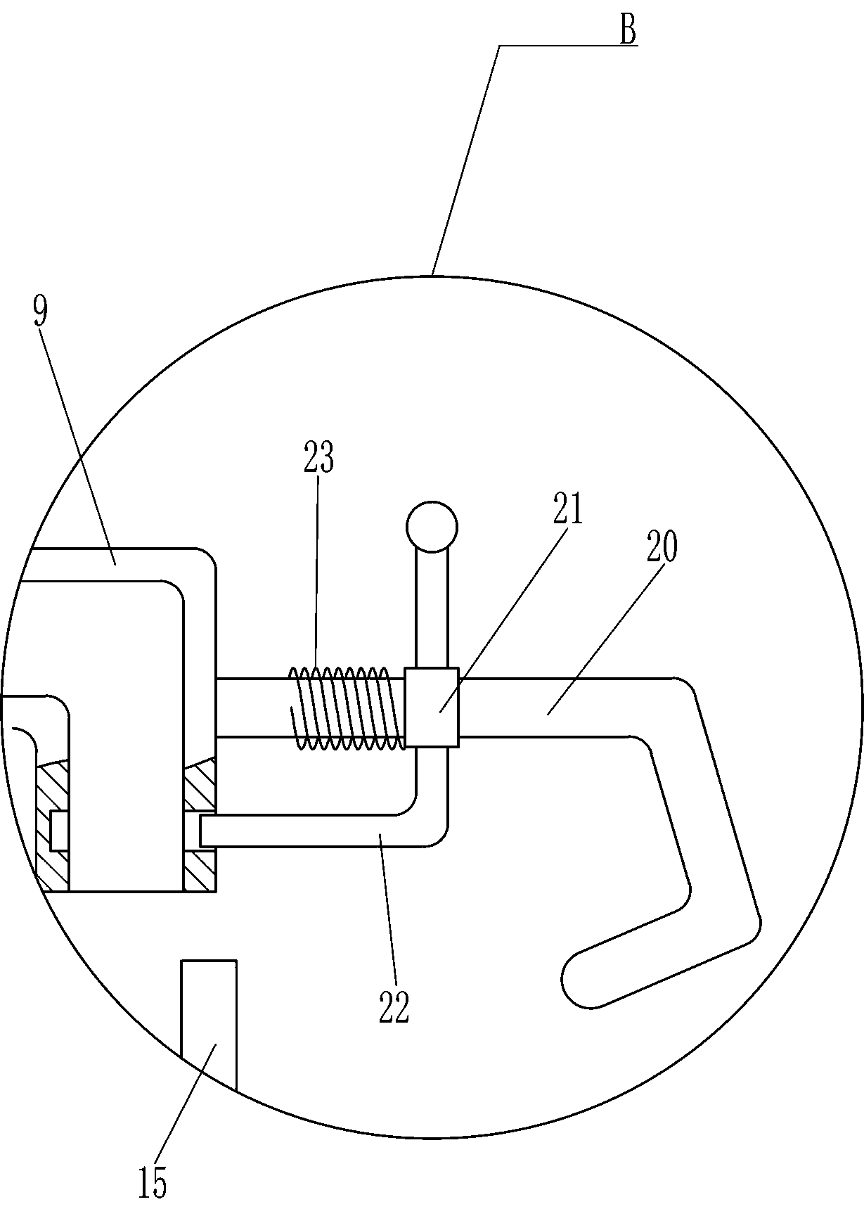
[0026] On the basis of Example 2, such as image 3 As shown, it also includes a sliding push handle 21, a transverse baffle plate 22 and a third compression spring 23, and a sliding push handle 21 is slidably connected to the turning handle 20, and the bottom of the sliding push handle 21 is provided with a transverse baffle plate 22, and the sliding push handle A third compression spring 23 is connected between the handle 21 and the handle 20 .

[0027] When the feeding tube 9 is turned counterclockwise by the handle 20, the sliding push handle 21 and its upper device are pushed to move to the left, and the transverse baffle 22 is snapped into the feeding tube 9, and the third compression spring 23 is compressed, passing through the horizontal baffle. 22. Prevent the beads in the feeding tube 9 from being thrown out during the rotation of the feeding tube 9, which saves the subsequent manual pick-up operation of the worker and achieves the effect of reducing the burden on the...


PUM


Abstract

The invention relates to bead stringing finishing equipment, in particular to bead stringing finishing equipment for ornament processing, which can collect and finish string beads easily and quickly package the string beads. The bead stringing finishing equipment for ornament processing comprises a mounting base, a transmission frame and the like. The transmission frame is arranged on one side ofthe mounting base. Through match between a conveying plate and devices on the conveying plate, scattered beads are automatically arranged in order, and subsequent packaging is facilitated; through match between a rotating handle and devices on the rotating handle, by means of a lever principle, the effect that the collecting frame is pushed through a long arm of force and small force is achieved;beads in a feeding pipe are prevented from being thrown out in the rotating process of the feeding pipe through a transverse baffle, the subsequent operation that workers need to pick up the beads manually is omitted, and the effect of reducing burdens of the workers is achieved.

Description

technical field [0001] The invention relates to a beading finishing device, in particular to a beading finishing device for ornament processing. Background technique [0002] Beads, most of the materials used are crystal, wood, agate, glass, amber and other textured beads. In recent years, it has gradually developed into a major category of handmade jewelry. People of different ages will also handcraft their favorite according to their own preferences. The beaded jewelry is deeply loved by people. [0003] The traditional bead packaging method requires people to manually arrange the produced beads neatly and then pack them. If some workers want to increase the speed of packaging beads, they will easily cause the beads to fall on the ground during the packaging process, which will greatly increase. Workers' follow-up workload, so it is necessary to find a device that facilitates the auxiliary arrangement of beads to replace the traditional manual packaging process. [0004]...

Claims


Application Information

Patent Timeline
IPC IPC(8): B65B35/30
CPCB65B35/30
Inventor 不公告发明人
Owner 肖松圣
Why Eureka
Try Eureka