
Superimposed slab shear wall structure

A technology of shear walls and laminated panels, applied to walls, building components, building structures, etc., can solve the problems of increased labor intensity, time-consuming and labor-intensive work, and low construction efficiency, so as to achieve simple structure and avoid wall skewing , Improve the effect of construction efficiency

Active Publication Date: 2020-03-24
南京市第二建筑设计院有限公司
View PDF9 Cites 0 Cited by
  • Summary
  • Abstract
  • Description
  • Claims
  • Application Information

AI Technical Summary

Problems solved by technology

[0004] However, before pouring the grout, it is necessary to bind and fix the prefabricated slab and the steel cage to avoid the inclination of the prefabricated slab. The current method of fixing the prefabricated slab and the steel cage is generally through steel wire binding. Because the steel wire is bound, it is time-consuming and laborious, which greatly increases Increased the labor intensity of the staff and low construction efficiency

Method used


Image

  • Superimposed slab shear wall structure
  • Superimposed slab shear wall structure
  • Superimposed slab shear wall structure

Examples


Embodiment

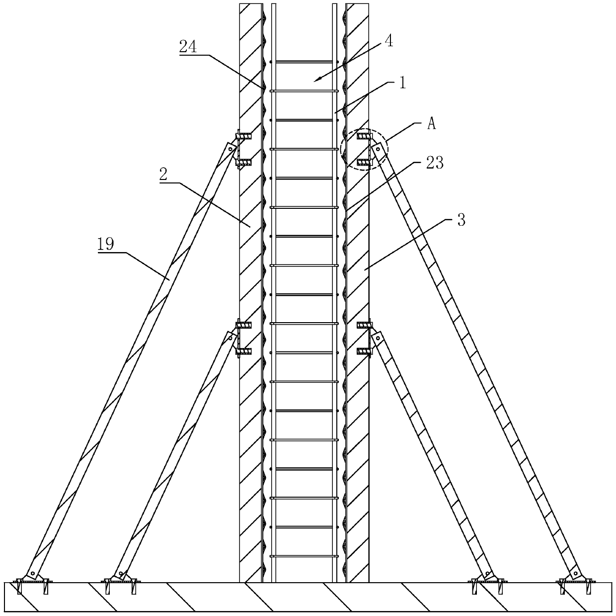
[0037] refer to figure 1, is a laminated plate shear wall structure disclosed by the present invention, comprising a reinforcement cage 1, the reinforcement cage 1 is bound and formed in a rectangular shape, an exterior wall panel 2 and an interior wall panel 3 are arranged on both sides of the reinforcement cage 1, and the interior wall A grouting space 4 for pouring concrete is enclosed between the board 3, the outer wall board 2 and the reinforcement cage 1; the inner wall board 3 and the outer wall board 2 are prefabricated boards, and concrete grout is poured into the grouting space 4, according to Design requirements, let it stand for a period of time to form a wall.

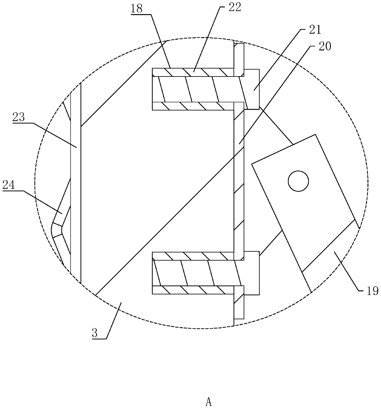
[0038] refer to figure 1 , the inner wall panel 3 and the outer wall panel 2 facing the side wall of the reinforcement cage 1 are evenly provided with a number of convex ribs 23, and a plurality of triangular reinforcing ribs 24 are uniformly distributed along the axial direction of the convex rib 23; Du...


PUM


Abstract

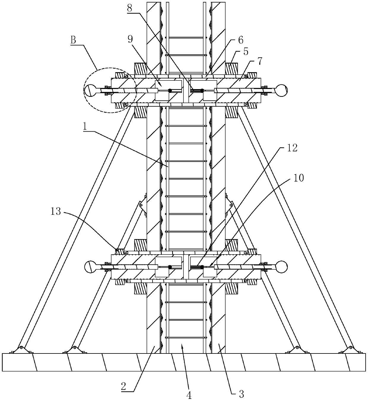
The invention relates to a superimposed slab shear wall structure. The structure comprises a reinforcement cage, an outer wallboard and an inner wallboard, wherein the outer wallboard and the inner wallboard are located on the two sides of the reinforcement cage, grouting space is defined among the inner wallboard, the outer wallboard and the reinforcement cage, the structure further comprises locking nuts, a plurality of sleeves, two guide posts and insertion blocks, wherein the plurality of sleeves are arranged in the grouting space in a penetrating manner, the two guide posts are oppositelyarranged in each sleeve, the insertion blocks are positioned on the two sides of the guide posts and are arranged in an L-shaped manner, the two ends of the sleeves extend out of the side wall of theinner wallboard and the side wall of the outer wallboard to be connected with the locking nuts, cavities are formed in the guide posts, driving assemblies for driving the two insertion blocks to extend into the grouting space are arranged in the cavities, the outer walls of the guide posts are provided with insertion holes for the insertion blocks to pass through, the outer walls of the sleevesare provided with adjustment holes in the axial direction corresponding to the insertion holes, each sleeve is internally provided with an adjusting piece for driving the two guide posts to slide relatively, the side walls, close to the reinforcement cage, of the outer wallboard and the inner wallboard are provided with a plurality of insertion grooves, and the horizontal ends of the insertion blocks penetrate through the reinforcement cage and extend into the insertion grooves. The shear wall structure facilitates fixation and positioning of the inner wallboard and outer wallboard, and the construction efficiency is high.

Description

technical field [0001] The invention relates to the technical field of shear walls, in particular to a laminated plate shear wall structure. Background technique [0002] Shear wall is also called wind-resistant wall, earthquake-resistant wall or structural wall. Laminated slab shear wall is a structural form of building industrialization and one of the main forms of modern prefabricated concrete structures. Water, material saving, shock absorption, greatly reducing construction waste, reducing noise pollution, reducing labor force, effectively improving the construction environment, and improving project quality. [0003] The existing laminated slab shear wall structure system consists of prefabricated parts and cast-in-place parts. The prefabricated part is a thin plate, which is completed in the prefabricated component processing plant and hoisted in place during construction; the core part of the shear wall is bound with steel bars on site. Concrete is poured, and at th...

Claims


Application Information

Patent Timeline
IPC IPC(8): E04B2/84E04B2/86E04G17/065
CPCE04B2/84E04B2/8629E04B2/8647E04G17/0655
Inventor 程永亮刘彧
Owner 南京市第二建筑设计院有限公司
Learn More