Large-flow floating ball switc
A technology of float switch and large flow, which is applied in the direction of lifting valve, valve details, engine components, etc., which can solve the problems of poor sealing and achieve good sealing effect
- Summary
- Abstract
- Description
- Claims
- Application Information
AI Technical Summary
Problems solved by technology
Method used
Image

Examples
Embodiment Construction
[0034] The present invention will be further described below in conjunction with the accompanying drawings.
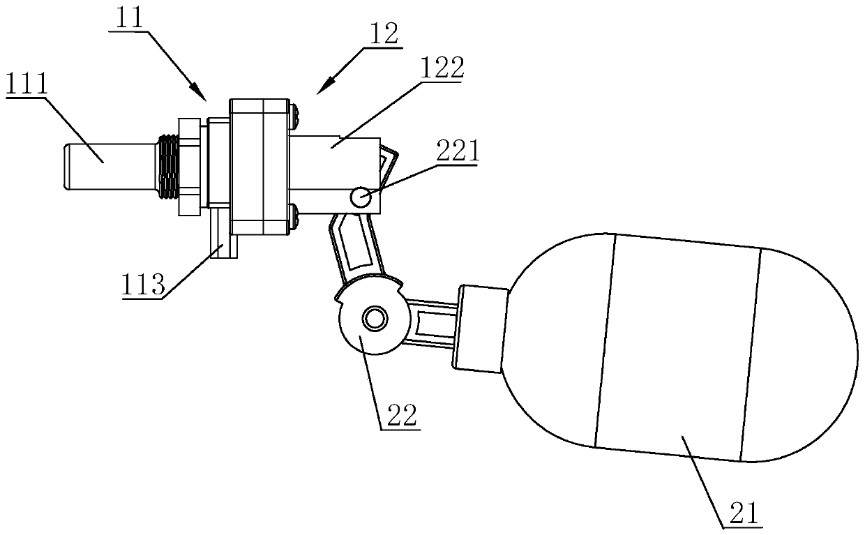
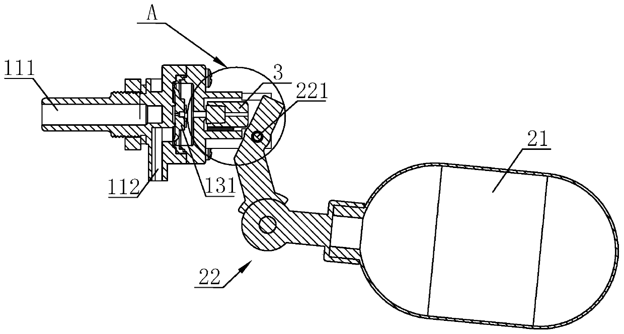
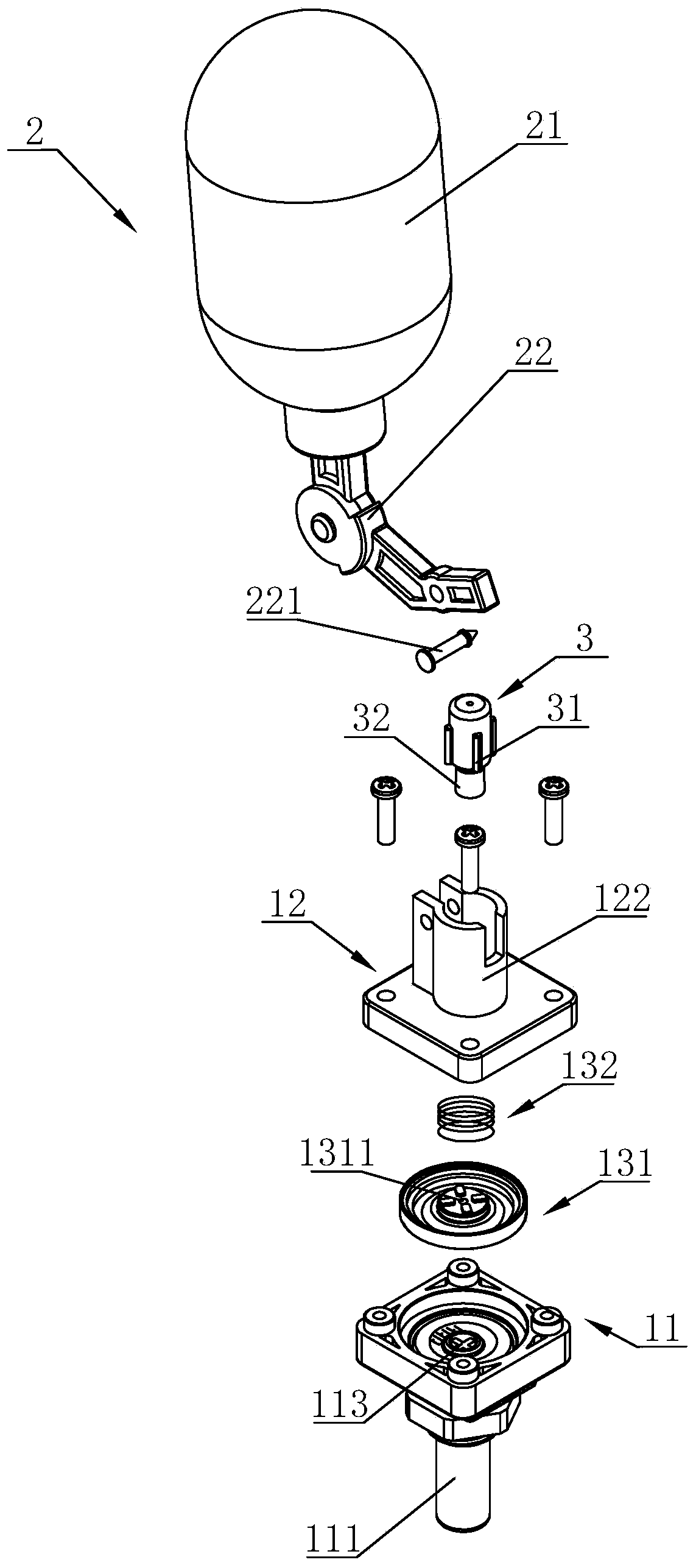
[0035] Such as Figures 1 to 7 A large flow float switch shown includes a switch body 1 and a float assembly 2. The float assembly 2 includes a float body 21 and a rocker arm 22. The float body 21 is mounted on the rocker arm 22, and the rocker arm 22 is rotatable. Installed on the body 1, the switch body 1 is provided with a valve chamber and a sealing assembly 13 located in the valve chamber, and one side of the switch body 1 is provided with a water inlet and a water outlet communicating with the valve chamber; the sealing assembly 13 is located at the valve The cavity is divided into a first valve cavity on one side and a second valve cavity on the other side; the sealing surface of the sealing assembly 13 can be sealed between the water inlet 111 and the water outlet 112; the other side of the switch body 1 is provided with a drain The pressure hole 121 and the p...
PUM
| Property | Measurement | Unit |
|---|---|---|
| Diameter | aaaaa | aaaaa |
Abstract
Description
Claims
Application Information
 - R&D
- Intellectual Property
- Life Sciences
- Materials
- Tech Scout
- Unparalleled Data Quality
- Higher Quality Content
- 60% Fewer Hallucinations
Browse by: Latest US Patents, China's latest patents, Technical Efficacy Thesaurus, Application Domain, Technology Topic, Popular Technical Reports.
© 2025 PatSnap. All rights reserved.Legal|Privacy policy|Modern Slavery Act Transparency Statement|Sitemap|About US| Contact US: help@patsnap.com