Eureka AIR delivers breakthrough ideas for toughest innovation challenges, trusted by R&D personnel around the world.

Buoy auxiliary installation platform of wave buoy calibrating device and buoy installation method

A verification device and wave buoy technology, applied in the direction of measuring devices, measuring the movement of open water sources, instruments, etc., can solve the problems of increased risk factor, large weight range, and deviation of position, so as to ensure installation accuracy and reduce work. Strength, the effect of increasing the safety factor

Pending Publication Date: 2020-03-24
国家海洋局北海标准计量中心
View PDF0 Cites 1 Cited by
  • Summary
  • Abstract
  • Description
  • Claims
  • Application Information

AI Technical Summary

Problems solved by technology

[0003] Because this installation method needs to be hoisted directly above the truss buoy fixture, because the weight range of the buoy is large, weighing hundreds of kilograms, when hoisting by driving, the risk factor is high, and the second is because the diameter of the buoy is nearly 1m. The width is nearly 2m. After the buoy falls into the fixture, the position may be misplaced. The staff need to probe their bodies into the inside of the truss through the gap of the truss to adjust. At this time, it may still be necessary to drive to assist in adjusting the position of the buoy. Restricted by the surrounding steel frame, the activity space is narrow, which greatly increases the risk factor
Since the installation of the buoy needs to tighten several screws in the circumferential direction, if there is only one installation worker, it is necessary to go to the other side to install the north side after installing the screws on the south side. The same narrow operating environment will inevitably increase The burden of personnel is not conducive to the installation and adjustment of buoys

Method used


Image

  • Buoy auxiliary installation platform of wave buoy calibrating device and buoy installation method
  • Buoy auxiliary installation platform of wave buoy calibrating device and buoy installation method
  • Buoy auxiliary installation platform of wave buoy calibrating device and buoy installation method

Examples


Embodiment Construction

[0038] In order to make the object, technical solution and advantages of the present invention clearer, the present invention will be further described in detail below in conjunction with the accompanying drawings and embodiments.

[0039] It should be noted that, in the description of the present invention, the terms "up", "down", "left", "right", "vertical", "horizontal", "inner", "outer" and the like indicate directions or positions The terms of the relationship are based on the orientation or positional relationship shown in the drawings, which are for convenience of description only, and do not indicate or imply that the device or element must have a specific orientation, be constructed and operated in a specific orientation, and therefore cannot be interpreted as Limitations on the Invention. In addition, the terms "first" and "second" are used for descriptive purposes only, and should not be understood as indicating or implying relative importance.

[0040] refer to ...


PUM


Abstract

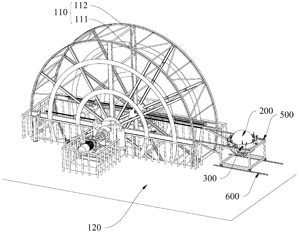
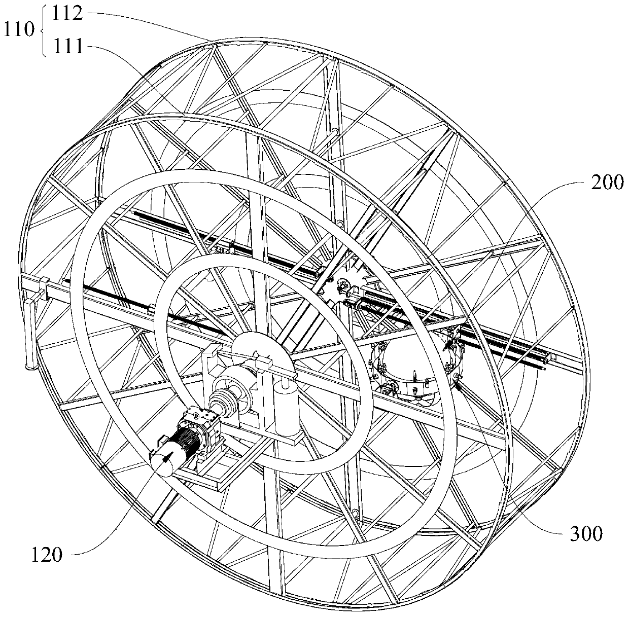
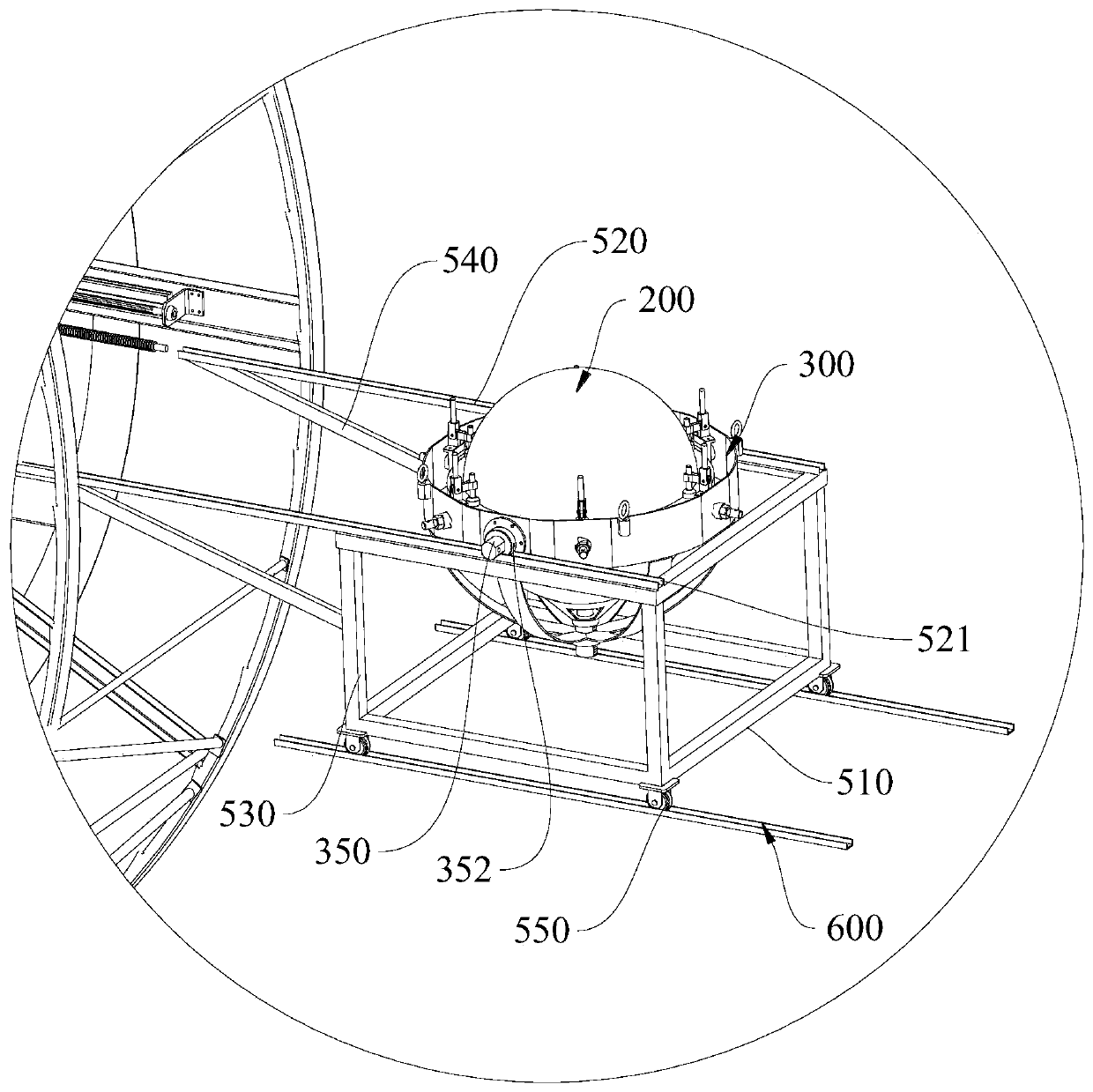
The invention discloses a buoy auxiliary installation platform of a wave buoy calibrating device and a buoy installation method. The buoy auxiliary installation platform comprises a supporting frame and a slideway, the slideway is arranged on a mounting platform of the double ring trusses and is positioned in an outer side area between a south ring truss and a north ring truss of the double ring trusses, and the supporting frame is arranged on the slideway in a sliding manner, is used for bearing a buoy fixture capable of fixing a buoy and can slide to a preset mounting position between the south ring truss and the north ring truss along the slideway, so that the buoy fixture is fixed on the double ring trusses. According to the auxiliary buoy mounting platform, the installation process ofthe buoy and the buoy fixture is moved out of the device, after the buoy is installed, the buoy is pushed into the double ring trusses through the slideway, and the buoy fixture and the double ring trusses can be rapidly fixed through the lock pins, so that the buoy installation work is completed, the safety coefficient of the buoy installation is greatly increased, the working intensity is reduced, and meanwhile the installation precision of the buoy and the buoy fixture is guaranteed.

Description

technical field [0001] The invention relates to the field of mechanical design of marine instruments, in particular to a buoy auxiliary installation platform and a buoy installation method of a wave buoy verification device. Background technique [0002] The wave buoy verification device can simulate the change of wave height and wave period, drive the buoy to be inspected to make sinusoidal or circular motion, simulate the movement of wave buoy in the ocean environment, and realize the buoy verification by processing the output data of the buoy and comparing it with the set value and adjustment purposes. The wave buoy verification device adopts a double-ring truss structure, the buoy is installed and fixed on the buoy fixture, and the verification is realized by the rotation of the buoy fixture on the truss. The existing technology is to connect the buoy fixture with the truss, and the buoy is transported to the verification laboratory by a forklift, then hoisted in the ai...

Claims


Application Information

Patent Timeline
IPC IPC(8): G01C25/00G01C13/00
CPCG01C25/00G01C13/004
Inventor 李明君秦平邢文斌张涛辛阿阿
Owner 国家海洋局北海标准计量中心
Why Eureka
Eureka Blog
Learn More