
Copper bar current-carrying capacity testing device and testing method

A technology for testing equipment and flow, which is applied in measuring equipment, environmental/reliability testing, and electrical measurement. It can solve problems such as excessive selection of copper bar specifications, small carrying capacity values, and impact on product quality, and achieve low production costs. , Improve product quality and reduce test cost

Pending Publication Date: 2020-03-24
RENERGY ELECTRIC TIANJIN
View PDF0 Cites 3 Cited by
  • Summary
  • Abstract
  • Description
  • Claims
  • Application Information

AI Technical Summary

Problems solved by technology

[0004] In the existing technology, the current carrying capacity of the copper bars is mostly obtained through calculation, and the value of the current carrying capacity obtained is mostly too small. As a result, in actual use, the specifications of the copper bars are selected too large, which causes waste and affects product quality.
[0005] In order to improve the accuracy of the value, the ampacity of the copper bar must be measured by the ampacity device of the copper bar. Most of the existing ampacity devices of the copper bar are complex in structure and require strict measurement conditions. As a result, the accuracy is low under different working conditions of copper bars

Method used


Image

  • Copper bar current-carrying capacity testing device and testing method
  • Copper bar current-carrying capacity testing device and testing method
  • Copper bar current-carrying capacity testing device and testing method

Examples


Embodiment Construction

[0032] The technical solutions of the present invention will be clearly and completely described below in conjunction with the accompanying drawings. Apparently, the described embodiments are some of the embodiments of the present invention, but not all of them. Based on the embodiments of the present invention, all other embodiments obtained by persons of ordinary skill in the art without making creative efforts belong to the protection scope of the present invention.

[0033] In the description of the present invention, it should be noted that the terms "center", "upper", "lower", "left", "right", "vertical", "horizontal", "inner", "outer" etc. The indicated orientation or positional relationship is based on the orientation or positional relationship shown in the drawings, and is only for the convenience of describing the present invention and simplifying the description, rather than indicating or implying that the referred device or element must have a specific orientation, ...


PUM


Abstract

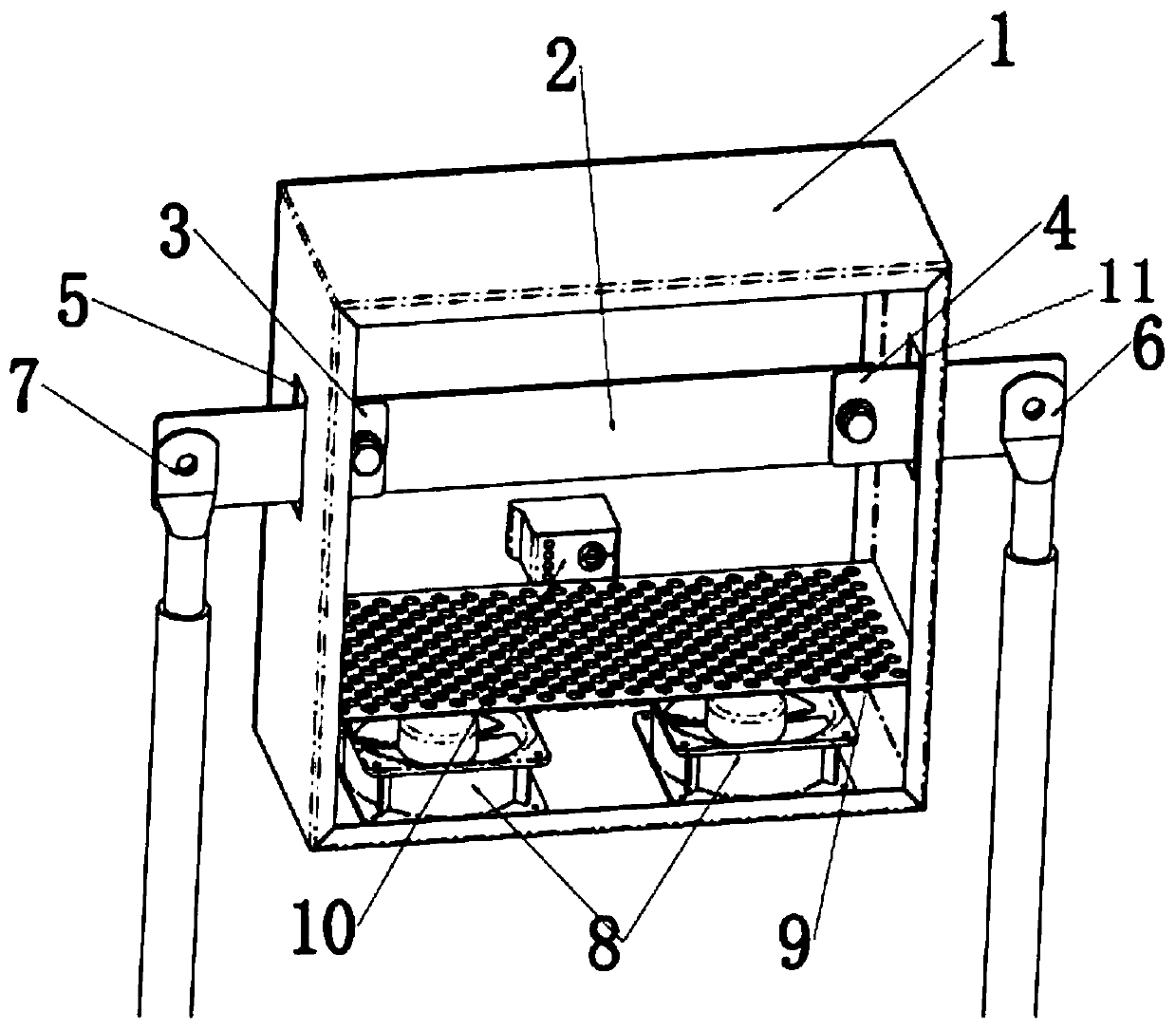
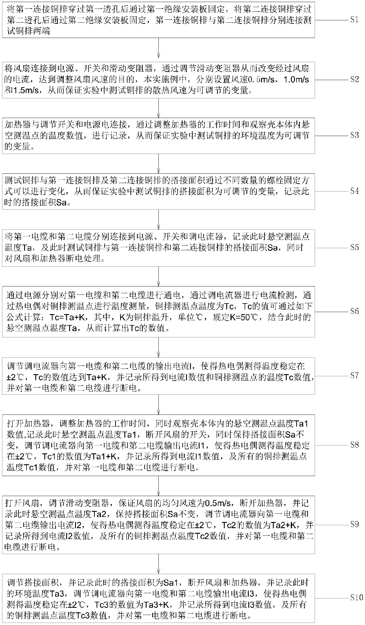
The invention provides a copper bar current-carrying capacity testing device including a shell body, a first through hole and a second through hole are respectively formed in opposite sides of the shell body; a first connecting copper bar is arranged in the first through hole; a second connecting copper bar is arranged in the second through hole; a test copper bar is arranged in the shell body, two ends of the test copper bar are respectively connected with one end of a first connecting copper bar and one end of a second connecting copper bar, the other end of the first connecting copper bar is connected with a first cable, the other end of the second connecting copper bar is connected with a second cable, and a plurality of temperature measuring points, a heater and a fan are arranged atthe bottom of the test copper bar. The device is simple in structure, convenient to operate and low in production cost, the test cost can be effectively reduced, the environmental factors of the copper bar can be adjusted, multiple groups of numerical values can be measured, and the copper bar current-carrying capacity measurement result is accurate. In actual use, waste caused by too large copperbar specification selection or risks caused by too small copper bar specification selection are reduced, and the product quality is improved.

Description

technical field [0001] The invention belongs to the technical field of copper bar testing, and in particular relates to a testing device and a testing method for carrying capacity of a copper bar. Background technique [0002] Copper bar refers to a long conductor made of copper material with a rectangular or chamfered (rounded) rectangular cross-section. It is generally called copper bus bar, copper bus bar or copper bus bar, and grounding copper bar. [0003] Copper busbar is a high-current conductive product, which is suitable for electrical engineering such as high and low voltage electrical appliances, switch contacts, power distribution equipment, and busway. It is also widely used in ultra-high current electrolytic smelting projects such as metal smelting, electrochemical plating, and chemical caustic soda. [0004] In the prior art, the ampacity of the copper bars is mostly calculated, and the values ​​of the ampacity obtained are mostly too small. As a result, in ac...

Claims


Application Information

Patent Timeline
IPC IPC(8): G01R31/00
CPCG01R31/00G01R31/003
Inventor 汤惠崴张新强左刚强邱庆恕
Owner RENERGY ELECTRIC TIANJIN
Learn More