Fiber distribution box capable of dissipating heat and preventing moisture

A technology of fiber distribution box and main body, which is applied in the field of heat dissipation and moisture-proof fiber distribution box, which can solve the problems of reducing the service life of electrical components, humidity of the fiber distribution box, and high temperature of the fiber distribution box, so as to avoid moisture, improve service life, and avoid temperature higher effect

Inactive Publication Date: 2020-03-24
杭州昱华科技有限公司
View PDF0 Cites 0 Cited by
  • Summary
  • Abstract
  • Description
  • Claims
  • Application Information

AI Technical Summary

Problems solved by technology

[0002] The optical fiber distribution box is an interface device used to connect the main optical cable and the distribution optical cable outdoors, in the corridor or indoors. The optical fiber distribution box must be able to work reliably in the specified environment, and its box can withstand a vertical pressure not greater than 500N , but the existing fiber distribution box still has the following problems: 1. It is impossible to cool the inside of the fiber distribution box, and the temperature inside the fiber distribution box will be high, thereby reducing the service life of electrical components; 2. The existing fiber distribution box The box cannot dry the moisture in the air, which will cause the inside of the fiber distribution box to be humid, which will cause the outer wall of the cable to conduct electricity and cause electric shock hazards

Method used


Image

  • Fiber distribution box capable of dissipating heat and preventing moisture
  • Fiber distribution box capable of dissipating heat and preventing moisture
  • Fiber distribution box capable of dissipating heat and preventing moisture

Examples


Embodiment Construction

[0020] The technical solutions in the embodiments of the present invention will be clearly and completely described below with reference to the accompanying drawings in the embodiments of the present invention. Obviously, the described embodiments are only a part of the embodiments of the present invention, rather than all the embodiments.

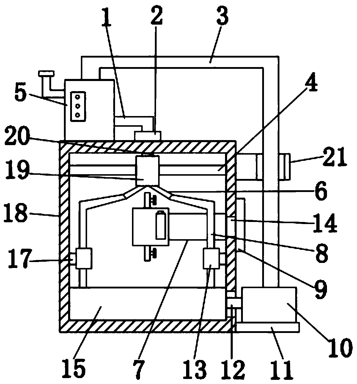
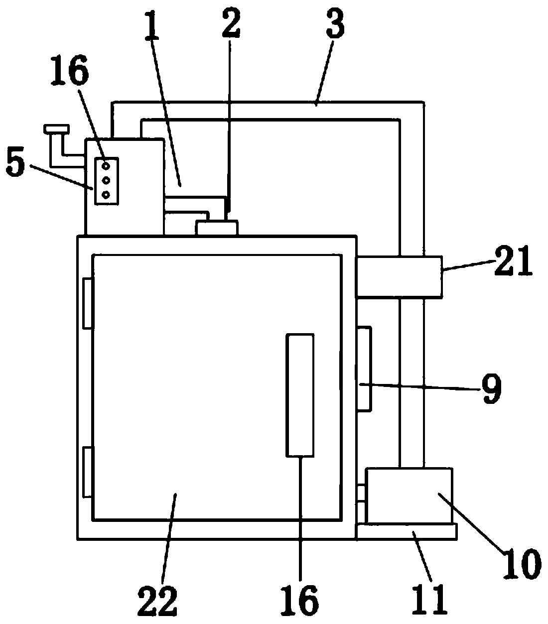
[0021] refer to Figure 1-6 , a heat-dissipating and moisture-proof fiber distribution box, including a fiber distribution box main body 18, a refrigeration device 5 is welded on the top left side of the fiber distribution box main body 18, and the water can be refrigerated by the refrigeration device 5, and the refrigeration device 5 includes Cylinder 504, the inner top of the cylinder 504 is welded with a support plate 502, the center of the top of the support plate 502 is welded with a collar 501, and a temperature sensor 509 is inserted inside the collar 501, through the temperature sensor 509 can detect the water temperature inside th...


PUM


Abstract

The invention discloses a fiber distribution box capable of dissipating heat and preventing moisture. The fiber distribution box comprises a fiber distribution box main body. A refrigerating device iswelded to the left side of the top end of the fiber distribution box body. A liquid outlet pipe is welded to the right side of the refrigerating device. An electromagnetic valve is welded at the bottom end of the liquid outlet pipe. A guide pipe is welded at the bottom end of the electromagnetic valve. A fixed cylinder is welded at the bottom end of the guide pipe. Transverse rods are welded to the left side and the right side of the fixing cylinder. The bottom end of the right side of the fiber distribution box main body is provided with a support plate. A water pump is installed at the topend of the supporting plate, the water pump is connected with the top end of a refrigerating device through a liquid return pipe, an air hole is formed in the center of the outer wall of the fiber distribution box body, a sealing plug is inserted into the air hole, and a gas drying device is welded to the left side of the fiber distribution box body. According to the invention, heat dissipation and cooling of the interior of the fiber distribution box can be realized, high temperature in the fiber distribution box is avoided, and the service life of electrical components is prolonged.

Description

technical field [0001] The invention relates to the technical field of fiber distribution boxes, in particular to a heat dissipation and moisture-proof fiber distribution box. Background technique [0002] The optical fiber distribution box is an interface device used to connect the main optical cable and the distribution optical cable outdoors, in the corridor or indoors. The optical fiber distribution box must be able to work reliably in the specified environment, and the box can withstand a vertical pressure of no more than 500N. However, the existing fiber distribution box still has the following problems: 1. The interior of the fiber distribution box cannot be dissipated and cooled, and the temperature inside the fiber distribution box will be higher, thereby reducing the service life of electrical components; 2. The existing fiber distribution box The box cannot dry the moisture in the air, which makes the inside of the fiber distribution box relatively humid, resultin...

Claims


Application Information

Patent Timeline
IPC IPC(8): G02B6/44
CPCG02B6/4446
Inventor 羊昱霖倪献明羊忠良朱军伟刘郑晓
Owner 杭州昱华科技有限公司
Why Eureka
Try Eureka