Master-slave control system and indication driving circuit thereof

A driving circuit and control system technology, applied in the direction of control/adjustment system, circuit monitoring/indication, circuit device, etc., can solve the problem of reducing the safety and reliability of the circuit control system, increasing the cost of circuit control system state display, multiple sub-circuits Module inconvenience and other issues, to achieve the effect of ensuring control efficiency and control stability, improving utilization efficiency and transmission accuracy, and ensuring control safety and flexibility

Pending Publication Date: 2020-03-24
SHENZHEN TANDA TECH +1
View PDF0 Cites 1 Cited by
  • Summary
  • Abstract
  • Description
  • Claims
  • Application Information

AI Technical Summary

Problems solved by technology

[0003] Since the circuit control system contains multiple sub-circuit modules, each sub-circuit module realizes a specific circuit function, and each sub-circuit module is in a corresponding operating state under integrated control, the circuit control system has high maneuverability and flexibility ; However, in the process of integrated control of multiple sub-circuit modules, users need to obtain the operating status or fault status of each sub-circuit module in real time to ensure the safety performance of the circuit control system; however, in order to obtain the operation of each sub-circuit module state, each sub-circuit module needs to transmit power separately to obtain the operating performance of the circuit module, which will not only generate a large power loss, increase the cost of the state display of the circuit control system, but also lead to wiring between multiple sub-circuit modules The structure is more complex, which brings great inconvenience to the circuit control process of multiple sub-circuit modules, and reduces the safety and reliability of the circuit control system

Method used


Image

  • Master-slave control system and indication driving circuit thereof
  • Master-slave control system and indication driving circuit thereof
  • Master-slave control system and indication driving circuit thereof

Examples


Embodiment Construction

[0053]In order to make the purpose, technical solution and advantages of the present application clearer, the present application will be further described in detail below in conjunction with the accompanying drawings and embodiments. It should be understood that the specific embodiments described here are only used to explain the present application, and are not intended to limit the present application.

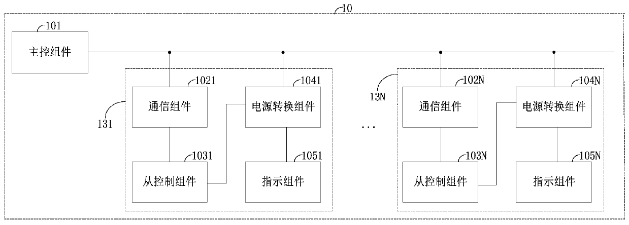
[0054] see figure 1 , a schematic structural diagram of the indicating drive circuit 10 applied to the master-slave control system provided by the embodiment of the present application, the indicating drive circuit 10 can display the status of each slave control unit in real time, so as to realize safe and efficient control for multiple slave control units The control function improves the flexibility and compatibility of the master-slave control process; in the process of indicating the status of each slave control unit, it realizes the multiplexing of electric energy, imp...


PUM


Abstract

An indication driving circuit applied to a master-slave control system and the master-slave control system are disclosed, the indication driving circuit comprises a master control assembly and at least one slave control unit, and each slave control unit comprises a communication assembly, a slave control assembly, a power conversion assembly and an indication assembly; the main control assembly isused for outputting a communication signal and a first power supply signal; the communication assembly is used for transmitting communication signals; the slave control assembly receives the communication signal and works according to the communication signal; the power supply conversion assembly is used for converting the first power supply signal to obtain a second power supply signal; the indication assembly displays the working state of the slave control assembly according to the second power supply signal; the working state of each slave control assembly can be displayed through the indication assembly, parallel control efficiency and control precision of the slave control assemblies are guaranteed, the indicating assembly directly takes electricity from the master control assembly through the bus, the utilization efficiency and precision of electric energy are improved, and an internal circuit structure and a wiring structure of the indicating drive circuit are simplified.

Description

technical field [0001] The present application belongs to the technical field of electronic circuits, and in particular relates to an indicating driving circuit applied to a master-slave control system and the master-slave control system. Background technique [0002] With the rapid development of current industrial technology, in order to meet the circuit function requirements in different fields, technicians need to carry out multi-functional design for the circuit control system to achieve more complete and comprehensive circuit functions; therefore, the circuit functions realized by the circuit control system are gradually becoming Due to the complexity and modularization, multiple sub-circuit modules are used in the circuit control system, and the master-slave control method is adopted. Different sub-circuit modules can communicate with each other compatiblely, so as to combine multiple sub-circuit modules to realize comprehensive circuit functions. Therefore, Taking in...

Claims


Application Information

Patent Timeline
Patent Type & Authority Applications(China)
IPC IPC(8): H02M3/00H02J7/00
CPCH02J7/0047H02J7/007H02M3/00
Inventor 万跃敏靳东风曾洁琼张天舜
Owner SHENZHEN TANDA TECH
Why Eureka
Try Eureka