Supercharge Your Innovation With Domain-Expert AI Agents!

Method for realizing array microphone beamforming

A microphone and array technology, applied in frequency/direction characteristic devices, sensors, electrical components, etc., can solve the problem of large frequency span of sound signals, achieve small calculation, reduce the need for array size, and enhance the effect of consistency

Active Publication Date: 2020-03-24
北京飞利信电子技术有限公司
View PDF5 Cites 1 Cited by
  • Summary
  • Abstract
  • Description
  • Claims
  • Application Information

AI Technical Summary

Problems solved by technology

Although the frequency span of the sound signal is very large, it is difficult to achieve ideal consistency in the spatial response of the array microphone in the entire frequency band under the limited array size and number of array elements.
But we can’t simply think that using a fixed or adaptive beamforming algorithm can achieve a good effect of array microphone voice interaction. After all, what the human ear receives is not a cold level, but a lot of subjectivity

Method used


Image

  • Method for realizing array microphone beamforming
  • Method for realizing array microphone beamforming
  • Method for realizing array microphone beamforming

Examples


Embodiment Construction

[0024] The specific technical solutions of the present invention are further described in the accompanying drawings of the structural description below.

[0025] A method for realizing array microphone beamforming according to the present invention is characterized in that it comprises the following steps,

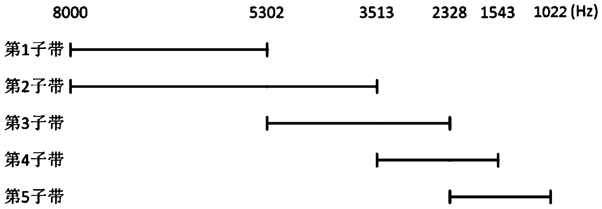
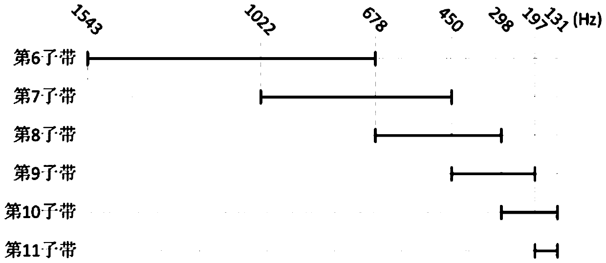
[0026] 1) Divide the sound range to be processed into high-frequency part a-b and low-frequency part b-c, where a>b>c, the value range of a is [4kHz, 16kHz], and the value range of b is [850Hz ,3.4kHz], the value range of c is [20Hz,1kHz]. For the value range of a, we know that the upper limit of the sensitive frequency range of the human ear is about 4kHz, and the upper limit can be extended in high sound quality requirements, but it is usually not relevant and will exceed 16kHz. For the value range of b, we generally think that the maximum aperture of our array d max Regarding, considering the limitations of physical equipment and the middle range of human speech, the ...


PUM


Abstract

The invention provides a method for realizing beam forming of an array microphone, which is characterized by comprising the following steps of: 1) dividing a sound range to be processed into a high-frequency part a-b and a low-frequency part b-c; 2) selecting a proportional constant R, and enabling c * Rm to be equal to b and b * Rn to be equal to a; 3) respectively taking [b * R0], [b * R1], [b *R2]-[b * Rn] as center frequencies, and calculating a binary array aperture corresponding to each center frequency; 4) decomposing each array element of the array microphone into sub-band signals, directly adding n + 1 sub-bands of a high-frequency part according to two array elements, and adding m sub-bands of a low-frequency part according to n + 2 array elements in a weighted manner; and 5) smoothly synthesizing all the sub-bands in the step 4) according to a Hamming window to obtain a spatial response in an a-c frequency range. Broadband signals are restored through array microphone aperture superposition and self-adaptive beam forming, few microphone units and small array sizes can be used, and good voice restoration quality is achieved.

Description

technical field [0001] The invention belongs to the technical field of voice signal processing, and in particular relates to a method for realizing array microphone beamforming. Background technique [0002] In live conference scenarios, the single-channel noise reduction method of dividing subbands, denoising subbands, and combining subbands with spectral subtraction has been widely used, but this method only suppresses the spectral components affected by noise, resulting in Distortion of the processed speech signal reduces speech quality and intelligibility. After learning from the application of arrays such as radars and antennas, people have designed array microphones with directivity. Array microphones have many advantages, for example, they do not need gooseneck microphones, which makes them more beautiful, and they are directional, which helps to suppress the interference of noise in the venue, and suppress the howling that may occur between audio equipment and speak...

Claims


Application Information

Patent Timeline
Patent Type & Authority Applications(China)
IPC IPC(8): H04R1/26
CPCH04R1/265
Inventor 杨振华曹忻军陈洪顺曹庆徐统业
Owner 北京飞利信电子技术有限公司
Features
  • R&D
  • Intellectual Property
  • Life Sciences
  • Materials
  • Tech Scout
  • Unparalleled Data Quality
  • Higher Quality Content
  • 60% Fewer Hallucinations
Learn More