
Connection device for a turbocharger, and turbocharger

A connection device, exhaust gas turbine technology, applied in the direction of gas turbine device, rod connection, exhaust device, etc., can solve the problems of connection device expansion, wrong positioning, etc., and achieve the effect of improving the resistance torque

Active Publication Date: 2020-03-24
IHI CHARGING SYST INT
View PDF9 Cites 0 Cited by
  • Summary
  • Abstract
  • Description
  • Claims
  • Application Information

AI Technical Summary

Problems solved by technology

[0006] Due to the high thermal load on the connecting device, possible expansion of the connecting device and subsequent incorrect positioning

Method used


Image

  • Connection device for a turbocharger, and turbocharger
  • Connection device for a turbocharger, and turbocharger
  • Connection device for a turbocharger, and turbocharger

Examples


Embodiment Construction

[0028] Exhaust turbocharger 1 in accordance with Figure 6 Constructed in the exemplary embodiment. The exhaust gas turbocharger 1 has a first housing section 2 in the form of a flow-through exhaust gas guide section 2 , which during operation of the exhaust gas turbocharger 1 is supplied by a fluid, usually by exhaust gas. flow through. Usually, but not necessarily, the exhaust gases are combustion products of an internal combustion engine, not shown in detail.

[0029] The exhaust gas turbocharger 1 is equipped with a second housing section 3 which is designed in the form of a bearing section and serves to support a not shown impeller of the exhaust gas turbocharger 1 . The bearing section 3 is located between a flow-through air guide section (not shown in detail) of the exhaust gas turbocharger 1 and the exhaust gas guide section 2 .

[0030] The impeller wheel (not shown in detail) has a compressor wheel (not shown in detail) and a turbine wheel (not shown in detail), w...


PUM


Abstract

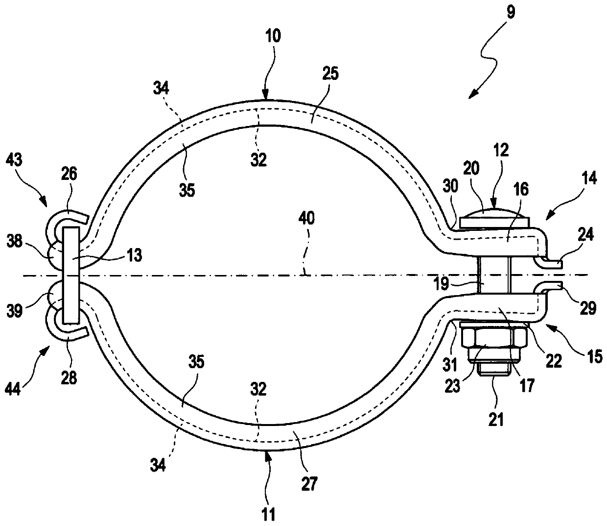
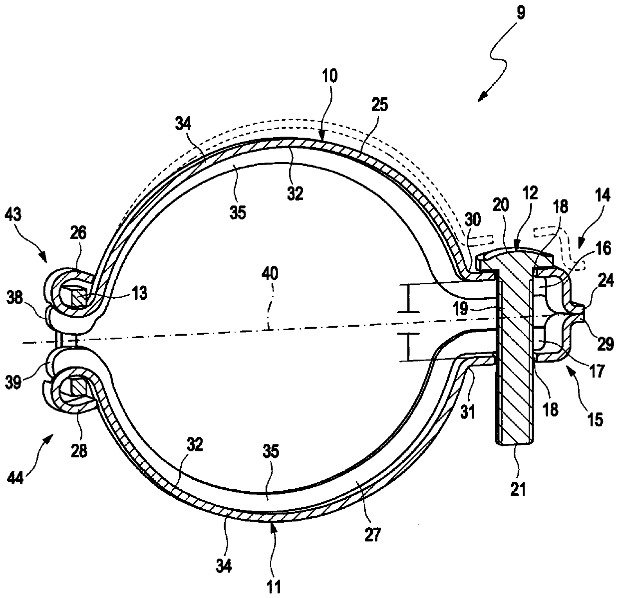
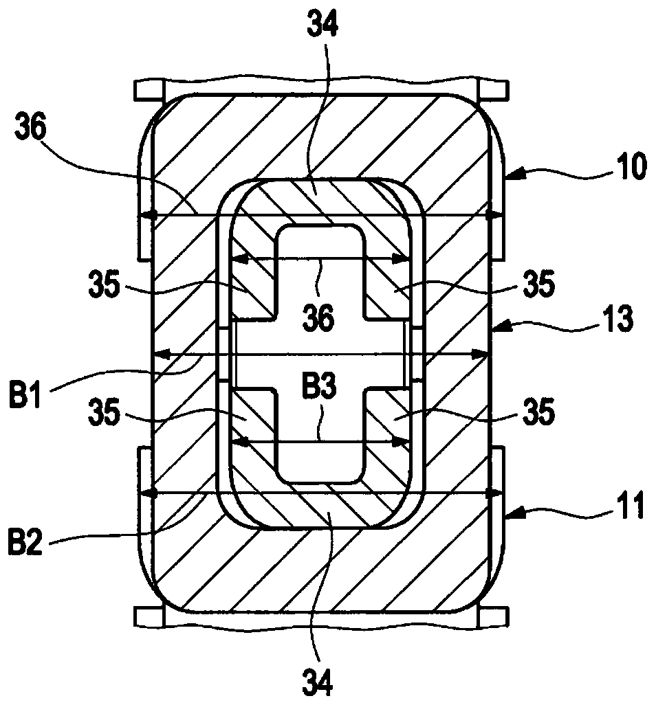
The invention relates to a connection device for a turbocharger, having a substantially bent first element (10) and a substantially bent second element (11), wherein: the first element (10), at a first end, has a radially extending first tensioning arm (16) and the second element (11), at a second end formed opposite the first end, has a radially extending second tensioning arm (17); a third end of the first element (10) formed facing away from the first end is formed opposite a fourth end of the second element (11) formed facing away from the second end and can be moved by means of said fourth end; the first tensioning arm (16) has a first stop (24) formed facing away from the third end and the second tensioning arm (17) has a second stop (29) opposite the first stop (24); the first tensioning arm (16) and the second tensioning arm (17) can be connected with the aid of a first connection element (12) of the connection device (9); and the second end and the fourth end can be movably connected together with the aid of a second connection element (13). According to the invention in order to reduce tensions in the two tensioning arms (16, 17), a transition (30; 31) is resiliently formed between the respective tensioning arm (16; 17) and a receiving portion (25; 27) of the corresponding element (10; 11), which receiving portion is arranged extending between the tensioning arm (16;17) and the third end or fourth end, wherein: the first element (10), at its first end portion (38) formed facing away from the first tensioning arm (16), is movably connected with the aid of the second connection element (13) to the second element (11) at its second end portion (39) formed facing away from the second tensioning arm (17); at least the first element (10) and / or the second element (11) at least in the region of the second connection element (13) has / have a profiled design; and the first element (10) and / or the second element (11) in the region of the second connection element (13) is / are designed so as to be capable of being enveloped by same. The invention also relates to a turbocharger (1) having a connection device (9).

Description

technical field [0001] The invention relates to a connection arrangement for an exhaust gas turbocharger of the type stated in the preamble of claim 1 . Furthermore, the invention relates to an exhaust gas turbocharger according to the preamble of claim 9 . Background technique [0002] The exhaust gas turbocharger expediently consists of a plurality of housing sections: a first housing section through which hot gas, usually exhaust gas of an internal combustion engine, usually flows; a second housing section, The second housing section is configured to accommodate an impeller, which is rotatably mounted in the second housing section and which is located between the first housing section and the third housing section. Between the body sections, generally ambient air can flow through the third housing section. Flange surfaces are formed between the individual housing sections in such a way that they are designed to be in contact with one another, so that the escape of hot a...

Claims


Application Information

Patent Timeline
Patent Type & Authority Applications(China)
IPC IPC(8): F01N13/18F16L23/08F16B7/18
CPCF01N13/1805F16B7/182F16L23/08F16B2/065F16B2/10F01N13/1855F01N2450/24Y02T10/12F01D25/243F01D25/28F02C6/12F05D2220/40F05D2250/13F05D2250/75F05D2250/90F05D2260/31
Inventor 法哈德·哈德达迪安克劳斯·斯珀林
Owner IHI CHARGING SYST INT
Learn More