
Motor unit and dust collector

A technology for motor units and vacuum cleaners, applied in the installation of vacuum cleaners, electrical equipment, cleaning equipment, etc., can solve problems such as poor layout of motor units, reduce processing costs, simplify fixing methods, and achieve good effects.

Pending Publication Date: 2020-03-27
XIAOGOU ELECTRIC INTERNET TECH BEIJING CO LTD
View PDF0 Cites 0 Cited by
  • Summary
  • Abstract
  • Description
  • Claims
  • Application Information

AI Technical Summary

Problems solved by technology

[0003] In view of the above analysis, the embodiment of the present invention aims to provide a motor unit and a vacuum cleaner to solve the problem of poor layout of the motor unit in the existing vacuum cleaner

Method used


Image

  • Motor unit and dust collector
  • Motor unit and dust collector
  • Motor unit and dust collector

Examples


Embodiment 1

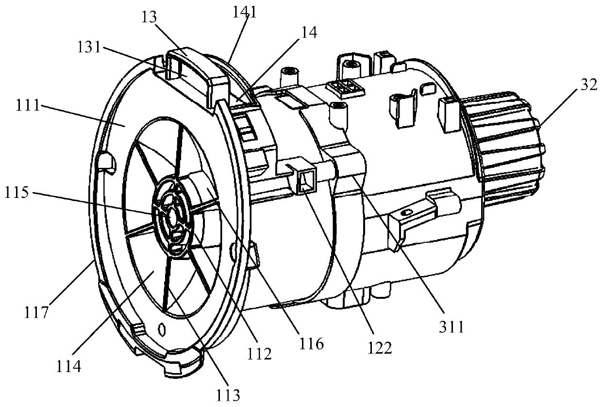
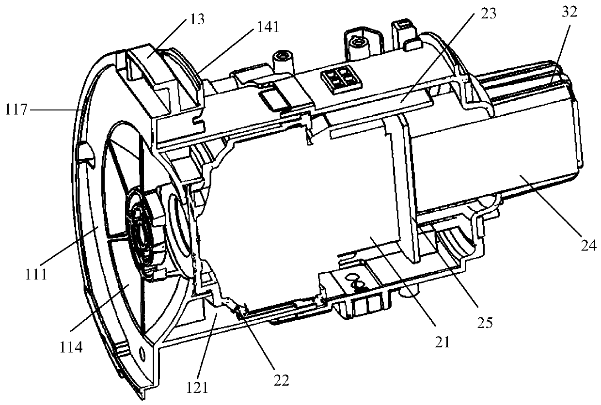
[0056] This embodiment provides a motor unit, such as Figure 1-Figure 4 As shown, it includes a front cover body 1, a motor assembly 2 and a rear cover body 3, and the motor assembly 2 is installed in a motor cover composed of the front cover body 1 and the rear cover body 3.

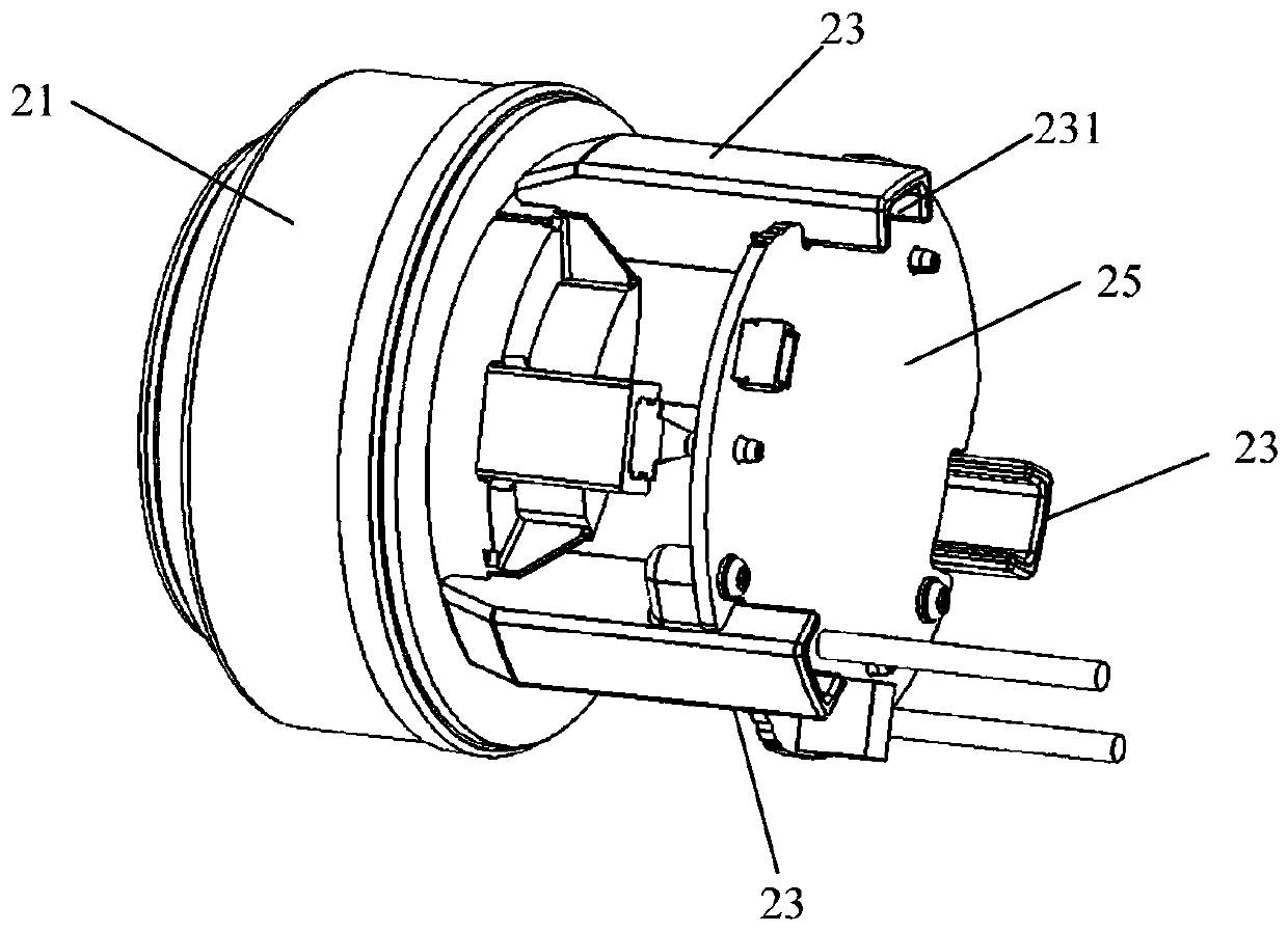
[0057] The motor assembly 2 includes a motor 21, a sealing sleeve 22, a gas guide plate 23, an air outlet filter 24 and a motor control board 25, and the sealing sleeve 22 is wrapped around the intake end of the motor 21; the motor control board 25 is located at the rear end of the motor 21, And be connected with motor 21, to control motor 21 work; The front end of gas guide plate 23 is docked with the gas outlet port of motor 21, and gas guide plate 23 surrounds the outside of air outlet filter 24, to the gas that motor 21 discharges quickly The air outlet filter 24 is guided;

[0058] Compared with the prior art, the motor 21 of this embodiment is clamped in the motor cover through the sealing sleev...

Embodiment 2

[0097] This embodiment provides a vacuum cleaner, such as Figure 5-Figure 10 As shown, it includes the motor unit, the exhaust assembly 4 and the casing 5 provided in the first embodiment.

[0098] The motor unit is installed on the rear end of the housing 5, and the air outlet grid portion 32 of the motor unit passes through the rear end surface of the housing 5, and the exhaust assembly 4 is covered on the air outlet grid portion 32, and is connected with the housing. The rear end surface of 5 is detachably connected, and the gas derived from the air outlet grid part 32 is discharged from the exhaust assembly 4 to the outside of the vacuum cleaner.

[0099] The exhaust assembly 4 includes an exhaust filter 41 and an exhaust hood 42 , and the exhaust hood 42 is provided with an exhaust assembly cavity for assembling the exhaust filter 41 .

[0100] The air exhaust filter 41 is provided with a grid assembly cavity 411 which can accommodate the air outlet grid part 32 , so th...


PUM


Abstract

The invention relates to a motor unit and a dust collector, belongs to the technical field of dust collectors, and solves the problem of poor layout of the motor unit in the existing dust collector. The motor unit comprises a motor cover and a motor assembly installed in the motor cover, and the motor assembly comprises a motor, a sealing sleeve, a gas guide plate, an air outlet filtering piece and a motor control panel; the sealing sleeve wraps the air inlet end of the motor; and the front end of the gas guide plate is butted with a gas outlet port of the motor. The motor is clamped in the motor cover through the front sealing sleeve and the air outlet filtering part, a rear sealing piece is not needed, the fixing mode of the motor is simplified, and the machining cost is reduced; the airoutlet filtering piece is arranged in the motor cover, the diameter of the motor unit can be effectively reduced, and therefore the size of the motor unit is reduced, and the overall size of the dustcollector is also reduced.

Description

technical field [0001] The invention relates to the technical field of vacuum cleaners, in particular to a motor unit and a vacuum cleaner. Background technique [0002] In the existing vacuum cleaner, the motor is generally fixed in the motor cover through the front sealing sleeve and the rear seal wrapped outside the front end of the motor, and the air outlet filter part is wrapped around the side of the motor cover to filter the gas discharged from the motor cover. In this way, the volume of the air outlet filter component is large, which in turn leads to an excessively large area for assembling the motor unit in the vacuum cleaner, which increases the overall size of the vacuum cleaner and affects the overall shape of the vacuum cleaner. Contents of the invention [0003] In view of the above analysis, the embodiment of the present invention aims to provide a motor unit and a vacuum cleaner to solve the problem of poor layout of the motor unit in the existing vacuum cl...

Claims


Application Information

Patent Timeline
Patent Type & Authority Applications(China)
IPC IPC(8): A47L9/28A47L9/00A47L5/24
CPCA47L5/24A47L9/00A47L9/28
Inventor 檀冲宋武斌程世及王东林润
Owner XIAOGOU ELECTRIC INTERNET TECH BEIJING CO LTD
Learn More