Manufacturing method for stacked iron core

A manufacturing method and iron core technology, which is applied in the field of laminated iron core-like iron core manufacturing, can solve the problems of concave shape burrs, low production efficiency, and increased production costs, and achieve high lamination coefficient and tensile strength, Save time for sorting and increase production efficiency

Active Publication Date: 2020-03-27
NINGBO ZHENYU TECH
View PDF10 Cites 2 Cited by
  • Summary
  • Abstract
  • Description
  • Claims
  • Application Information

AI Technical Summary

Problems solved by technology

[0002] At present, laminated iron cores can be used as motor iron cores, transformer iron cores, etc. The iron core is a kind of upper and lower iron chips stacked on each other and then fixed by welding or glue, which has problems such as hindering magnetic flux, and Ordinary workers cannot complete such high-demand iron core welding. If there is a piece of welding that does not correspond, the motor will not work normally. Therefore, it is necessary to hire professional workers. Professional welding workers are expensive, which increases production costs. The iron chips are stacked together, and the production efficiency is not high due to the method of sheet arrangement. Therefore, a progressive die is developed to form the buckle points while stamping the iron chips, and each iron chip is stacked on each other by the buckle points after being punched out. The iron core is formed by riveting, but there are still buckling points in the formed iron core. The iron core with buckling points has large eddy current loss and poor flatness during use, and is prone to concave pieces and burrs on the shape when punching. and other problems, so there is an urgent need for a laminated iron core manufacturing process and structure that can solve the above problems

Method used


Image

  • Manufacturing method for stacked iron core
  • Manufacturing method for stacked iron core
  • Manufacturing method for stacked iron core

Examples


Embodiment

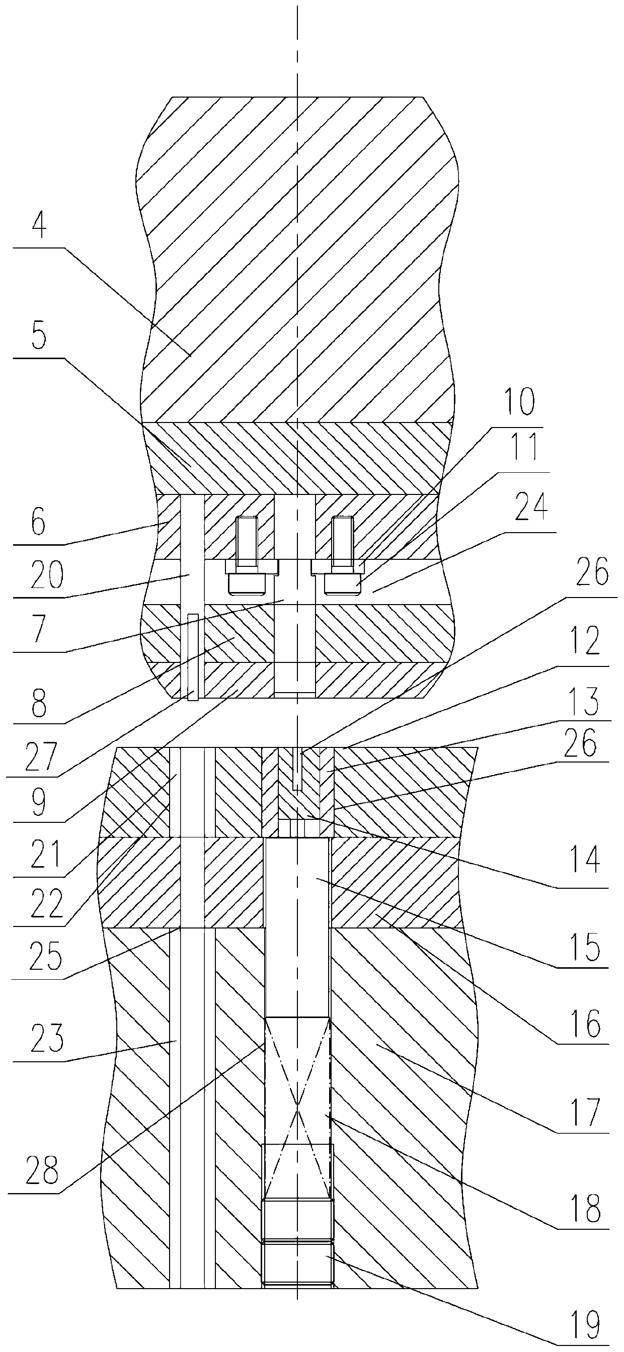
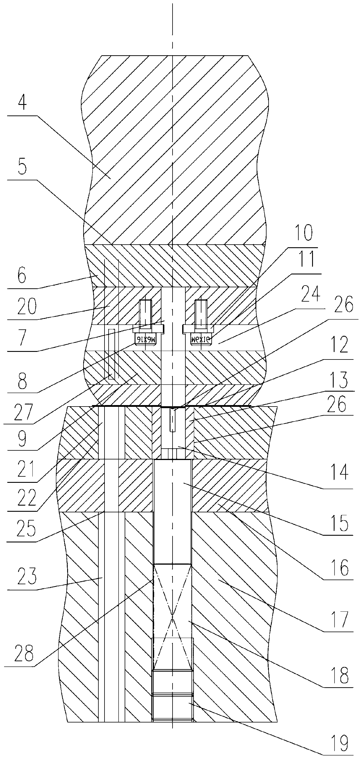
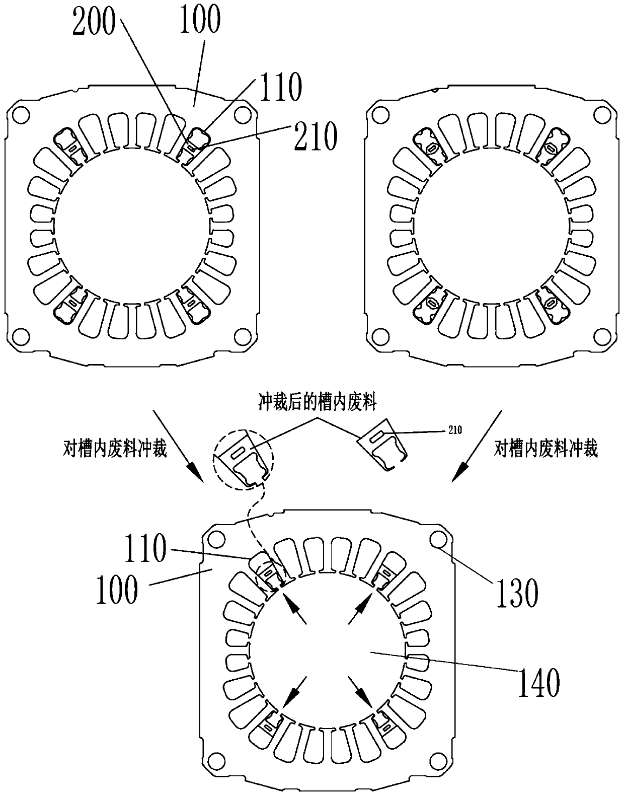
[0032] Such as Figure 1-Figure 6 As shown, the manufacturing method of the laminated iron core described in this embodiment, its specific manufacturing steps include the following:

[0033] S1. Use the punch of the stamping die to punch out a plurality of iron chips 100 one by one on the processing sheet. When the iron chips 100 are punched down, a central hole, a round hole 120 and / or a through groove 110 are formed on the iron chips, and interference fit The waste material 300 fixed in the round hole 120 or the through groove 110 and the buckle point 210 on the waste material 200, the through groove is positioned at the inner side wall of the center hole or the outer peripheral side of the iron chip; if it is processed by a progressive die, it should first The center hole is punched out, and then the circular hole 120 and / or the through groove 110, the waste material 300 fixed on the circular hole 120 or the through groove 110 with an interference fit, and the buckle point ...


PUM


Abstract

The invention discloses a manufacturing method for a stacked iron core. The manufacturing method for the stacked iron core comprises the steps that multiple iron core pieces are punched in a machiningpiece one by one through a male die of a punching die, central holes, circular holes and / or through grooves, waste materials fixed in the circular holes or the through grooves in an interference fitmode and buckling points on the waste materials are formed in the iron core pieces while the iron core pieces are punched, and the through grooves are located in the inner side walls of the central holes or the outer circumferential sides of the iron core pieces; the multiple iron core pieces with the waste materials are stacked and then riveted through the buckling points, and the stacked iron core is formed; the waste materials in the through grooves are radially pushed to be radially separated from the through grooves; and a plurality of pits are formed in the inner side walls of the circular holes through punching in the step 1, a plurality of grooves and a plurality of convex blocks are formed in the outer circumferential walls of the waste materials in the circular holes, the end side faces of the convex blocks are closely attached to the inner side walls of the circular holes, and after the waste materials in the punched circular holes are rotated or radially pushed, the waste materials in the circular holes are in a suspended state and automatically fall to be separated from the circular holes. According to the method, the using performance is better, and the stacked iron core is perfect after being formed.

Description

technical field [0001] The invention relates to the technical field of manufacturing a laminated iron core, in particular to a manufacturing method of a laminated iron core. Background technique [0002] At present, laminated iron cores can be used as motor iron cores, transformer iron cores, etc. The iron core is a kind of upper and lower iron chips stacked on each other and then fixed by welding or glue, which has problems such as hindering magnetic flux, and Ordinary workers cannot complete such high-demand iron core welding. If there is a piece of welding that does not correspond, the motor will not work normally. Therefore, it is necessary to hire professional workers. Professional welding workers are expensive, which increases production costs. The iron chips are stacked together, and the production efficiency is not high due to the method of sheet arrangement. Therefore, a progressive die is developed to form the buckle points while stamping the iron chips, and each i...

Claims


Application Information

Patent Timeline
IPC IPC(8): B21D35/00B21D28/02B21D28/34B21D39/02B21D28/14B21D37/10B21D37/08B21D45/00B21D43/20
CPCB21D28/02B21D28/14B21D28/34B21D35/001B21D37/08B21D37/10B21D39/02B21D43/20B21D45/00
Inventor 周茂伟钟丽祝黄秀东
Owner NINGBO ZHENYU TECH
Why Eureka
Try Eureka