Molten metal liquid directional conveying assembly for casting machining

A technology for molten metal and components, which is applied in the field of directional conveying components for molten metal liquid in casting processing, which can solve the problems such as the inability to adjust the length of the ladle, high ambient temperature, and high risk factor, so as to ensure life, health and safety, and the principle is simple , reduce the effect of baking

Inactive Publication Date: 2020-03-27
六安七茗道机电科技有限公司
View PDF7 Cites 0 Cited by
  • Summary
  • Abstract
  • Description
  • Claims
  • Application Information

AI Technical Summary

Problems solved by technology

[0002] Pouring refers to pouring molten metal, concrete, etc. into the mold for casting of metal parts or molding of cement boards and concrete buildings. Manually filling into the mold to realize pouring, the technical problem is that the length of the ladle cannot be adjusted, and the operator is close to the molten metal, and the heat radiated by the molten metal will form a high-temperature baking for the operator. The ambient temperature perceived by personnel is high, the comfort is poor, and at the same time, the risk factor is large. In order to solve the above technical problems, it is necessary to provide a telescopic molten metal pouring telescopic mold with ingenious structure, simple principle, convenient operation and adjustable length. Lever

Method used


Image

  • Molten metal liquid directional conveying assembly for casting machining
  • Molten metal liquid directional conveying assembly for casting machining
  • Molten metal liquid directional conveying assembly for casting machining

Examples


Embodiment Construction

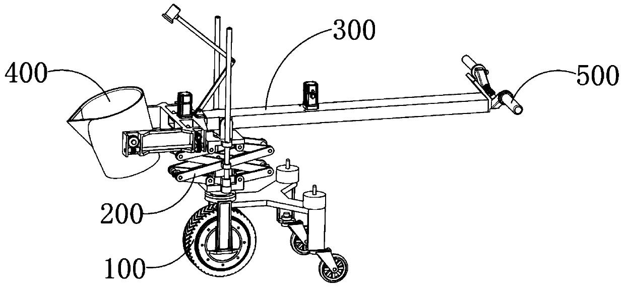
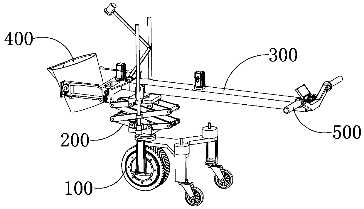
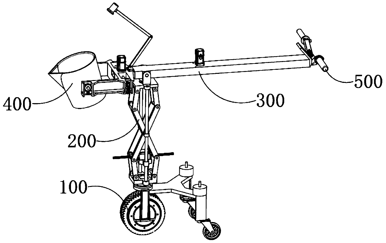
[0051] see Figure 1-29, an electric control molten metal pouring assistant, which includes a traveling mechanism 100, a lifting mechanism 200, a telescopic mechanism 300, a bucket 400 for containing molten metal, and a control armrest 500. The traveling mechanism 100 is arranged on the ground, and the telescopic mechanism 300 is located on the Directly above 100, the lifting mechanism 200 is located between the travel mechanism 100 and the telescopic mechanism 300 and its lower end is fixedly connected to the travel mechanism 100, and its upper end is fixedly connected to the telescopic mechanism 300. The bucket 400 is arranged on the telescopic end of the telescopic mechanism 300 and can Overturning setting, the control armrest 500 is arranged on the fixed end of the telescopic mechanism 300 and can control the forward and backward of the traveling mechanism 100, control the raising and lowering of the lifting mechanism 100, control the extension and shortening of the telesco...


PUM


Abstract

The invention provides a molten metal liquid directional conveying assembly for casting machining. The molten metal liquid directional conveying assembly comprises a rectangular hollow outer cylinderand an inner cylinder which are nested with each other, and the rectangular hollow outer cylinder and the inner cylinder form sliding guide fit in the length direction of the rectangular hollow outercylinder and the inner cylinder. The length direction of the outer cylinder and the inner cylinder are both horizontally set, and the length of the outer cylinder is greater than the length of the inner cylinder. The inner cylinder is sleeved with the outer cylinder and can slide outwardly from one end opening of the inner cylinder. The end, away from the outer cylinder, of the inner cylinder is atelescopic end, and the end, away from the inner cylinder, of the outer cylinder is a fixed end and is an operator holding end. In the initial state, the telescopic end of the inner cylinder extendsout of the outer cylinder and is fixedly provided with two fork-shaped mounting frames. The mounting frames are fixedly provided with containing barrels used for containing molten metal liquid. The molten metal liquid directional conveying assembly has the beneficial effects that the telescopic control over the containing barrels in the horizontal direction is facilitated, the safe distance can bekept between the operators and the containing barrels, the baking of the operators is reduced by reducing the heat radiation of the molten metal liquid, the comfort of the operators is improved, andthe life health safety of the operators is guaranteed.

Description

technical field [0001] The invention relates to the technical field of pouring, in particular to a molten metal directional conveying component for casting processing. Background technique [0002] Pouring refers to pouring molten metal, concrete, etc. into the mold for casting of metal parts or molding of cement boards and concrete buildings. Manually filling into the mold to realize pouring, the technical problem is that the length of the ladle cannot be adjusted, and the operator is close to the molten metal, and the heat radiated by the molten metal will form a high-temperature baking for the operator. The ambient temperature perceived by personnel is high, the comfort is poor, and at the same time, the risk factor is large. In order to solve the above technical problems, it is necessary to provide a telescopic molten metal pouring telescopic mold with ingenious structure, simple principle, convenient operation and adjustable length. Lever. Contents of the invention ...

Claims


Application Information

Patent Timeline
Patent Type & Authority Applications(China)
IPC IPC(8): B22D41/12B22D41/06
CPCB22D41/06B22D41/12
Inventor 胡能静费先江张冠
Owner 六安七茗道机电科技有限公司
Why Eureka
Try Eureka