Supercharge Your Innovation With Domain-Expert AI Agents!

A puller for disassembling special-shaped deep groove ball bearings

A technology for deep groove ball bearings and bearings, applied in the field of disassembly of special-shaped deep groove ball bearings, can solve problems such as surface damage, waste, and bumping of parts, and achieve the goals of avoiding bumps, saving quality costs, and improving decomposition quality Effect

Active Publication Date: 2021-01-26
SHENYANG LIMING AERO-ENGINE GROUP CORPORATION
View PDF7 Cites 0 Cited by
  • Summary
  • Abstract
  • Description
  • Claims
  • Application Information

AI Technical Summary

Problems solved by technology

[0004] Since this kind of bearing is the main rotor load-bearing part of the engine, it needs to be disassembled for inspection every time it is repaired. However, there is currently no special puller that can disassemble this kind of bearing. The current disassembly method is to disassemble it first. The upper half ring of the inner ring of the bearing, and then divide the outer ring and the roller with the mandrel, and finally divide the inner ring and the lower half ring
However, during the process of disassembling the bearing, the rollers will be in a scattered state, and the rollers are easy to collide with each other or other parts, resulting in damage to the surface of the rollers. Every year, about 20 sets of bearings are scrapped because the surface of the rollers exceeds the standard. , resulting in a huge waste of

Method used


Image

  • A puller for disassembling special-shaped deep groove ball bearings
  • A puller for disassembling special-shaped deep groove ball bearings
  • A puller for disassembling special-shaped deep groove ball bearings

Examples


Embodiment Construction

[0019] The present invention will be described in detail below in conjunction with the accompanying drawings and embodiments.

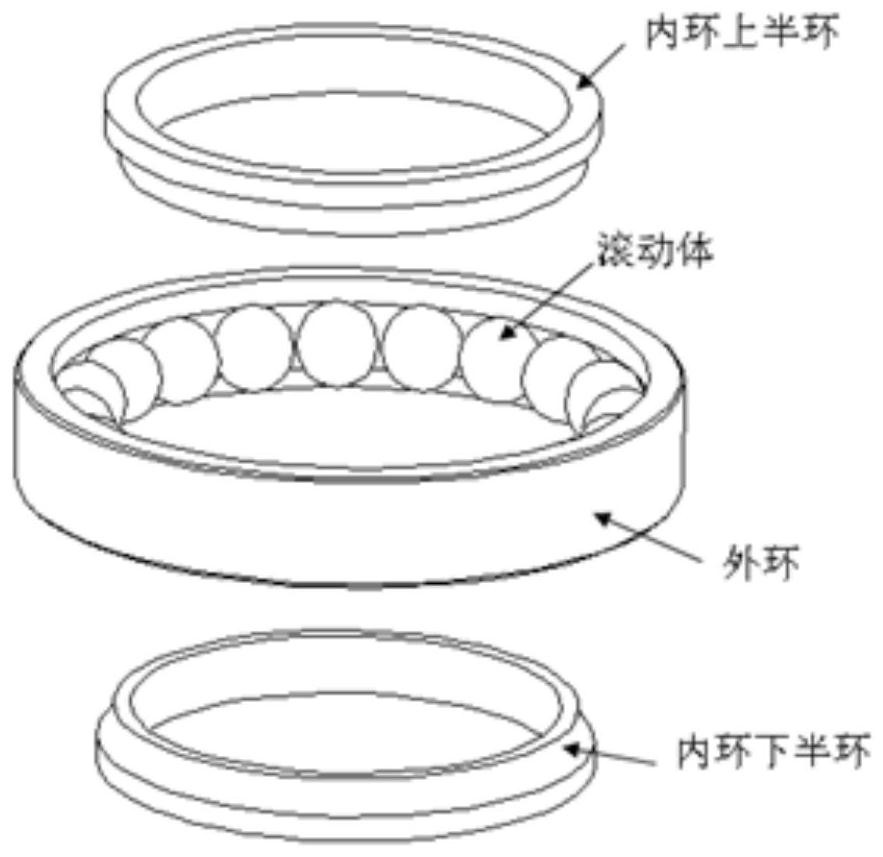
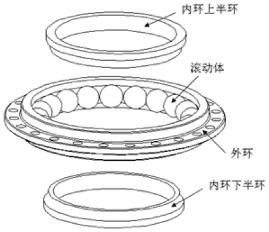
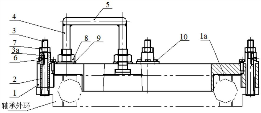
[0020] Such as Figure 1-4 As shown, a puller for disassembling a special-shaped deep groove ball bearing includes a base 1; the lower surface of the base 1 is provided with a ring groove 1a matching the upper surface of the outer ring of the bearing, which is used to locate the outer ring of the bearing. After the puller is installed, Ensure that the bearing rolling body does not move or fall; the edge of the base 1 is provided with a through hole corresponding to the process hole on the outer ring of the bearing, and a tensioning mechanism is provided in the through hole. The tensioning mechanism includes a clamp spring 2, a tensioning mechanism Rod 3, positioning piece 6 and nut 7, clamp spring 2 is fixed in the through hole through fastener 10 (screw), expansion rod 3 is arranged in clamp spring 2, and anti-rotation chute 3a is provided on the out...


PUM


Abstract

The invention discloses a puller for disassembling a special-shaped deep groove ball bearing, which comprises a base; the lower surface of the base is provided with a ring groove matching the upper surface of the bearing outer ring; The through hole corresponding to the process hole on the upper surface is provided with a tensioning mechanism in the through hole, and the tensioning mechanism includes a clamp spring, an expansion rod, a positioning piece and a nut, and the clamp spring is fixed on the through hole through a fastener. Inside, the expansion rod is set in the clamp spring, and the outer surface of the expansion rod is provided with an anti-rotation chute, and the expansion rod and the clamp spring are positioned in the anti-rotation chute through the positioning part to prevent the rotation of the expansion rod , the upper part of the expansion rod is threaded with a nut, by tightening the nut, the expansion rod moves up in the clamp spring, and the clamp spring expands outward through the tapered surface of the lower part of the expansion rod, forming an interference with the process hole on the mounting edge of the outer ring of the bearing The outer ring of the bearing is fixed; the upper surface of the base is fixed with a lifting mechanism, and the puller and the outer ring of the bearing are pulled out together through the lifting mechanism.

Description

technical field [0001] The invention relates to the disassembly of special-shaped deep groove ball bearings, and in particular provides a puller for disassembly of special-shaped deep groove ball bearings. Background technique [0002] Deep groove ball bearing is a very common type of rolling bearing with a wide range of uses. This bearing can bear both radial load and axial load. Most deep groove ball bearings are shaped like figure 1 As shown, the outer ring has no mounting edge, and it is compressed with a large nut during installation. For structural needs, deep groove ball bearings are sometimes designed as figure 2 the shape shown. [0003] The structural feature of this kind of bearing is that the outer ring has a mounting edge, and there are process holes, bolt holes and pin holes on the mounting edge. When assembling, pins are used to position the outer ring of the bearing, and the pin and the outer ring are interference fit. The outer ring is fixed, and the pr...

Claims


Application Information

Patent Timeline
Patent Type & Authority Patents(China)
IPC IPC(8): B25B27/00F16C43/04
CPCB25B27/00F16C43/04
Inventor 余相如杨东张贺李博韩强
Owner SHENYANG LIMING AERO-ENGINE GROUP CORPORATION
Features
  • R&D
  • Intellectual Property
  • Life Sciences
  • Materials
  • Tech Scout
  • Unparalleled Data Quality
  • Higher Quality Content
  • 60% Fewer Hallucinations
Learn More