Steel plate conveying and positioning device

A positioning device, steel plate technology, applied in conveyors, conveyor objects, transportation and packaging, etc., can solve problems such as inability to transport different types of steel plates, inability to implement steel plate transportation and noise reduction, and inability to reach designated locations, etc. Achieve the effect of improving stability and safety, improving use safety, sliding stability and convenience

Inactive Publication Date: 2020-03-27
ZHEJIANG CONSTR ENG GRP CO LTD
View PDF7 Cites 2 Cited by
  • Summary
  • Abstract
  • Description
  • Claims
  • Application Information

AI Technical Summary

Problems solved by technology

[0005] 1. The steel plate on the conveying roller table slips, which makes the conveying process ineffective
[0006] 2. The steel plate placed on the conveying roller table is offset and cannot reach the designated pos

Method used


Image

  • Steel plate conveying and positioning device
  • Steel plate conveying and positioning device
  • Steel plate conveying and positioning device

Examples


Embodiment 1

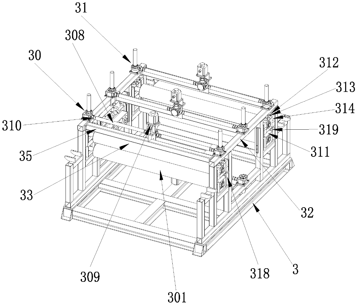
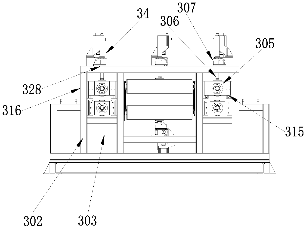
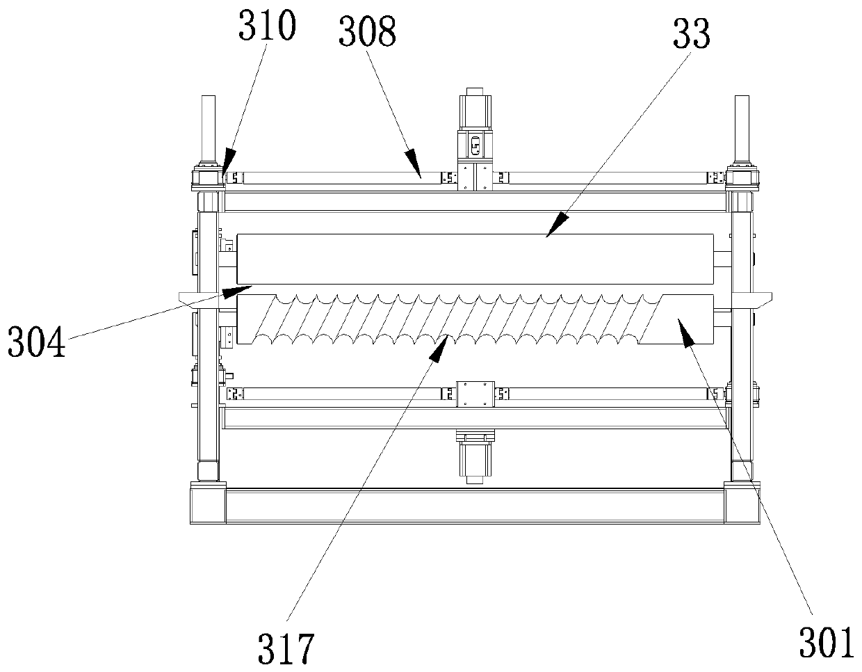
[0033] Embodiment 1: as Figure 1-3 As shown, a steel plate conveying and positioning device includes a base 3, a front positioning mechanism 30 and a rear positioning mechanism 31 fixed on the base 3 and arranged oppositely, and a horizontal bar 32 is fixed on the front positioning mechanism 30 and the rear positioning mechanism 31 and connecting rod 35; the front positioning mechanism 30 includes two support rods 302 symmetrically arranged with a delivery roller 301, and a guide groove 303 is formed between the two support rods 302, and the two ends of the delivery roller 301 are assembled in the guide groove 303. Driven by a driving motor, a pressure roller 33 is arranged on the conveying roller 301, and an adjustment mechanism 34 for adjusting the up and down movement of the pressure roller 33 is arranged on the conveying roller 301, and a passage 304 for steel plate conveying is formed between the pressure roller 33 and the conveying roller 301. Mechanism 34 drives pressu...


PUM


Abstract

The invention relates to a steel plate conveying and positioning device, which includes a base, and a front positioning mechanism and a rear positioning mechanism that are fixedly arranged on the baseand opposite to each other. A horizontal rod and a connecting rod are fixedly arranged on the front positioning mechanism and the rear positioning mechanism. The front positioning mechanism includesa conveying roller and two support rods arranged symmetrically. A guide groove is formed between the two support rods. The conveying roller has both ends assembled in a guide groove and is driven by adriving motor. A pressure roller is arranged on the conveying roller. An adjusting mechanism for moving the pressure roller up and down is arranged on the pressure roller. A steel plate conveying channel is formed between the pressure roller and the conveying roller. The adjusting mechanism drives the pressure roller to move, and then drives the pressure roller to get close to or away from the conveying roller. A spiral groove is disposed on the conveying roller to help to adjust the steel plate when the steel plate comes into contact with the conveying roller, to make the steel plate run smoothly in the overall running process of a conveying roller table, and to prevent the steel plate from slipping on the conveying roller table and causing invalid operation.

Description

technical field [0001] The invention belongs to the technical field of steel plate processing, and in particular relates to a steel plate conveying and positioning device. Background technique [0002] With the rapid development of my country's national economy, my country's demand for steel is also greatly increasing. In many construction sites, steel pipes are used to build the outer frame. During the long-distance transportation of steel plates, due to the weight of the steel plates, there are The disadvantages of weak stability, difficult control, and large shaking affect the quality of subsequent processing. [0003] When cutting or derusting steel plates, it is necessary to use rollers to transport the steel plates. Among them, the existing conveying rollers often slip and run ineffectively, and there is a lack of guide bars on both sides of the conveying rollers. , it often happens that the conveying direction of the steel plate deviates and fails to reach the designa...

Claims


Application Information

Patent Timeline
IPC IPC(8): B65G13/06B65G13/11B65G39/02B65G47/24
CPCB65G13/06B65G13/11B65G39/02B65G47/24B65G2201/022
Inventor 尤可坚丁宏亮赵峰李毅刘泽裕邱甜金睿张少君肖锋蒋燕芳陈志杰袁方
Owner ZHEJIANG CONSTR ENG GRP CO LTD
Why Eureka
Try Eureka