Working method of mechanical hands for carrying tires
A working method and manipulator technology, applied in the field of manipulators, can solve the problem of heavy manual handling workload, and achieve the effects of reducing equipment costs, improving stability and safety, and maintaining balance.
- Summary
- Abstract
- Description
- Claims
- Application Information
AI Technical Summary
Problems solved by technology
Method used
Image
Examples
Embodiment 1
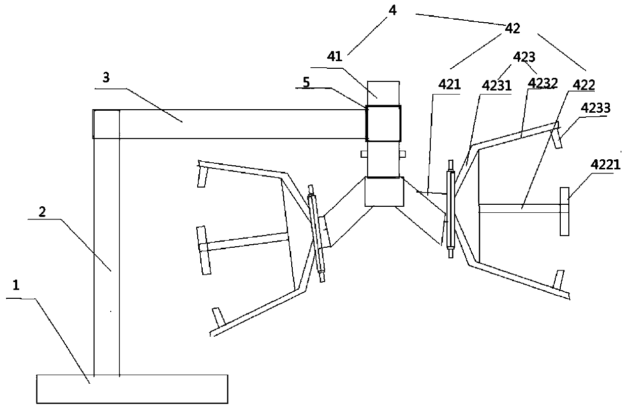
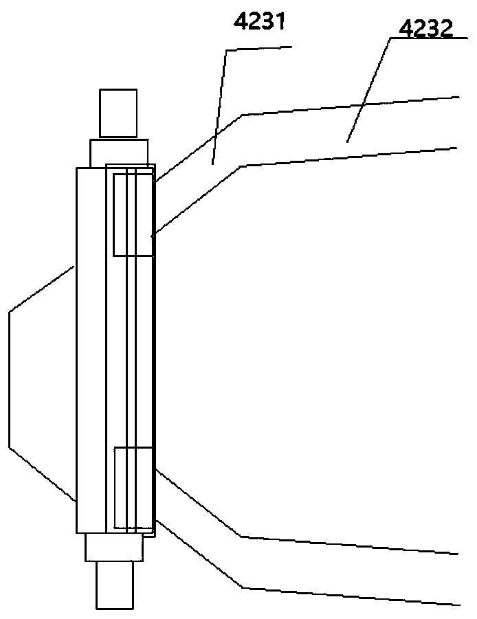
[0034] As shown in the figure, a working method of a manipulator for handling tires, comprising: a base 1, a column 2, a mechanical arm 3 and a group of manipulators 4, the column 2 is arranged on the base 1, and the mechanical arm 3 Installed on the column 2, the manipulator 4 is installed on the manipulator 3; the manipulator 4 is provided with a suspension frame 41 and a grabbing hand 42, and the suspension frame 41 is installed on the installation shaft 5 of the manipulator 3, so A group of grasping hands 42 are oppositely arranged on the suspension frame 41 , the grasping hands 42 are arranged symmetrically and misplaced, and the installation shaft 5 and the mechanical arm 3 are arranged in a rotating manner.
[0035] Further, the grabbing hand 42 is provided with a mounting seat 421, a support rod 422 and a handle bar 423, the support rod 422 is arranged in the middle of the mounting seat 421, and the handle bar 423 is arranged at the center of the mounting seat 421. aro...
Embodiment 2
[0038] As shown in the figure, a working method of a manipulator for handling tires, comprising: a base 1, a column 2, a mechanical arm 3 and a group of manipulators 4, the column 2 is arranged on the base 1, and the mechanical arm 3 Installed on the column 2, the manipulator 4 is installed on the manipulator 3; the manipulator 4 is provided with a suspension frame 41 and a grabbing hand 42, and the suspension frame 41 is installed on the installation shaft 5 of the manipulator 3, so A group of grasping hands 42 are oppositely arranged on the suspension frame 41 , the grasping hands 42 are arranged symmetrically and misplaced, and the installation shaft 5 and the mechanical arm 3 are arranged in a rotating manner.
[0039] Further, the grabbing hand 42 is provided with a mounting seat 421, a support rod 422 and a handle bar 423, the support rod 422 is arranged in the middle of the mounting seat 421, and the handle bar 423 is arranged at the center of the mounting seat 421. aro...
Embodiment 3
[0047] As shown in the figure, a working method of a manipulator for handling tires, comprising: a base 1, a column 2, a mechanical arm 3 and a group of manipulators 4, the column 2 is arranged on the base 1, and the mechanical arm 3 Installed on the column 2, the manipulator 4 is installed on the manipulator 3; the manipulator 4 is provided with a suspension frame 41 and a grabbing hand 42, and the suspension frame 41 is installed on the installation shaft 5 of the manipulator 3, so A group of grasping hands 42 are oppositely arranged on the suspension frame 41 , the grasping hands 42 are arranged symmetrically and misplaced, and the installation shaft 5 and the mechanical arm 3 are arranged in a rotating manner.
[0048] Further, the grabbing hand 42 is provided with a mounting seat 421, a support rod 422 and a handle bar 423, the support rod 422 is arranged in the middle of the mounting seat 421, and the handle bar 423 is arranged at the center of the mounting seat 421. aro...
PUM
 Abstract
Description
Claims
Application Information
 - R&D
- Intellectual Property
- Life Sciences
- Materials
- Tech Scout
- Unparalleled Data Quality
- Higher Quality Content
- 60% Fewer Hallucinations
Browse by: Latest US Patents, China's latest patents, Technical Efficacy Thesaurus, Application Domain, Technology Topic, Popular Technical Reports.
© 2025 PatSnap. All rights reserved.Legal|Privacy policy|Modern Slavery Act Transparency Statement|Sitemap|About US| Contact US: help@patsnap.com


