Energy-saving chemical fiber silk cutting machine

A silk cutting machine, energy-saving technology, applied in fiber processing, fiber cutting, textiles and papermaking, etc., can solve the problems of cutting failure, chemical fiber tow fixation, and easy deviation of cutting knives, etc., and achieve the effect of improving cutting efficiency

Inactive Publication Date: 2020-03-27
长兴县新盛纺织有限公司
View PDF0 Cites 0 Cited by
  • Summary
  • Abstract
  • Description
  • Claims
  • Application Information

AI Technical Summary

Problems solved by technology

[0004] The present invention provides an energy-saving chemical fiber cutting machine, which can effectively solve the problem that the chemical fiber bundle is not fixed during the cutting process and the cutting knife is prone to deviation, which leads to the failure of cutting.

Method used


Image

  • Energy-saving chemical fiber silk cutting machine
  • Energy-saving chemical fiber silk cutting machine
  • Energy-saving chemical fiber silk cutting machine

Examples


Embodiment

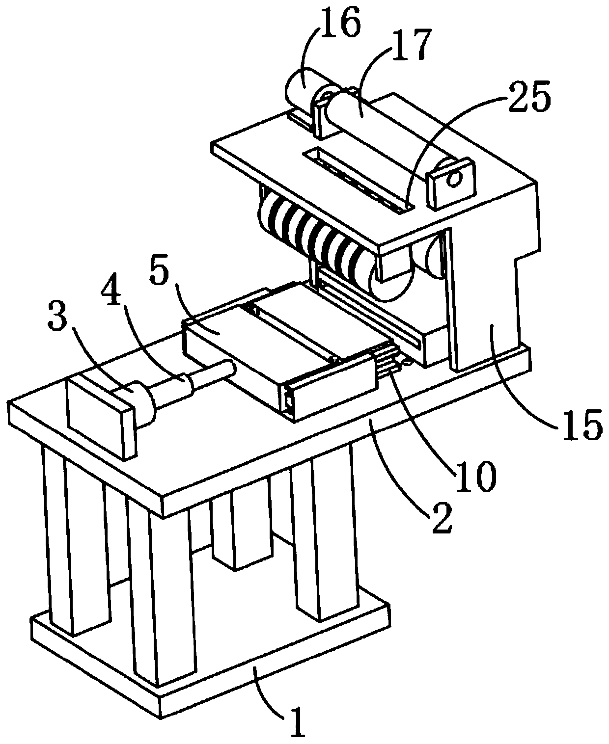
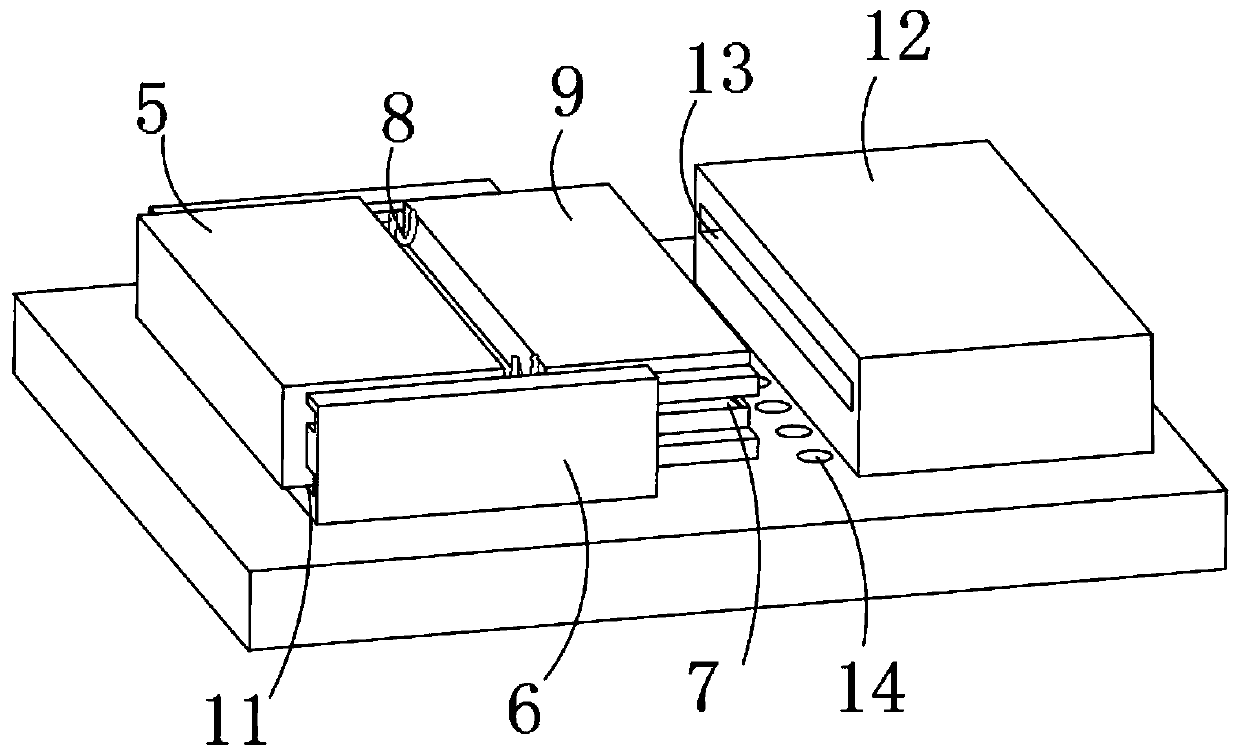
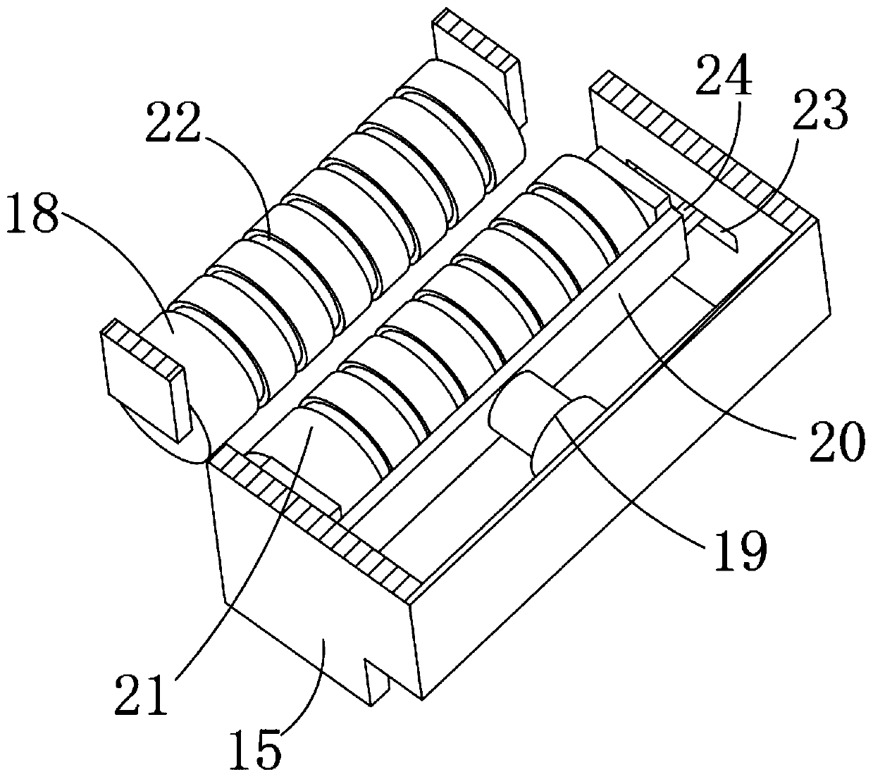
[0024] Example: such as Figure 1-3 As shown, the present invention provides a technical solution, an energy-saving chemical fiber cutting machine, a processing platform 2 is installed on the top of the base 1, a mounting seat 6 is installed in the middle of the top of the processing platform 2, and a mounting seat 6 is installed in the middle of the mounting seat 6. Groove 11, the top of the processing platform 2 is located on one side of the mounting seat 6, and a cylinder 3 is installed. One end of the cylinder 3 is connected to a telescopic rod 4, and one end of the telescopic rod 4 is connected to a push block 5. The push block 5 is embedded and installed in the installation groove. Inside of 11, a cutting tool 7 is installed in the middle of one end of the push block 5 away from the telescopic rod 4, and one end of the push block 5 is located at the two sides of the cut tool 7 and is symmetrically installed with an extrusion spring 8, and one end of the extrusion spring 8...


PUM


Abstract

The invention discloses an energy-saving chemical fiber silk cutting machine. A mounting seat is mounted in the middle of the top end of a processing platform; an air cylinder is mounted on one side of the mounting seat at the top of the processing platform; one end of the air cylinder is connected with a telescopic rod; one end of the telescopic rod is connected with a pushing block; a cutting tool is mounted in the middle of the end, far away from the telescopic rod, of the pushing block; the two sides of the cutting tool at one end of the pushing block are symmetrically provided with extrusion springs; one end of each extrusion spring is connected with a pressing block; a fixed seat is mounted at the end, far away from the air cylinder, of the top of the processing platform; and a cutting groove is formed in the middle of the end, close to the corresponding pressing block, of the fixed seat. According to the cutting machine, the pushing block is used for driving the pressing blocksand the cutting tool to move forwards simultaneously to cut chemical fiber silk, the chemical fiber silk is fixed before the cutting tool touches the chemical fiber silk through cooperation of the pressing blocks and the extrusion springs, and the chemical fiber silk is cut through cooperation of the cutting tool and the cutting groove, so that deviation of cutting is avoided.

Description

technical field [0001] The invention relates to the technical field of chemical fiber cutting, in particular to an energy-saving chemical fiber cutting machine. Background technique [0002] A round shaft with a pulley is installed on the workbench, a round blade is fixedly installed on the round shaft, and a motor is installed on the lower part of the workbench, and the motor is driven by a belt to install the round blade. The circular shafts are connected, and the motor is used to drive the circular blade to rotate and cut. When cutting in this way, the circular blade and the chemical fiber will constantly rub at high speed to generate heat, causing scalding at the incision of the chemical fiber. For this reason, the Chinese patent discloses a chemical fiber cutting machine, which is convenient for cutting multiple chemical fibers at the same time. The two knives cooperate with each other, and the shearing is carried out by using the shear distance, and the service life i...

Claims


Application Information

Patent Timeline
Patent Type & Authority Applications(China)
IPC IPC(8): D01G1/00
CPCD01G1/00
Inventor 朱新平
Owner 长兴县新盛纺织有限公司
Why Eureka
Try Eureka