Engine lubricating oil cooling system

A cooling system and engine technology, applied in the direction of engine cooling, engine lubrication, engine components, etc., can solve the problems of small fuel flow and insufficient heat dissipation of lubricating oil.

Inactive Publication Date: 2020-03-27
AECC SICHUAN GAS TURBINE RES INST
View PDF9 Cites 7 Cited by
  • Summary
  • Abstract
  • Description
  • Claims
  • Application Information

AI Technical Summary

Problems solved by technology

[0004] Purpose of the invention: In order to solve the above problems, the present invention provides a "fuel oil radiator + air oil radiator" solution, which is used to solve the problem caused by the small fuel flow of high-altitude cruising aero-engines at high altitude and low speed. Insufficient heat dissipation of lubricating oil

Method used


Image

  • Engine lubricating oil cooling system
  • Engine lubricating oil cooling system
  • Engine lubricating oil cooling system

Examples


Embodiment Construction

[0025] The present invention will be further explained below in conjunction with accompanying drawing:

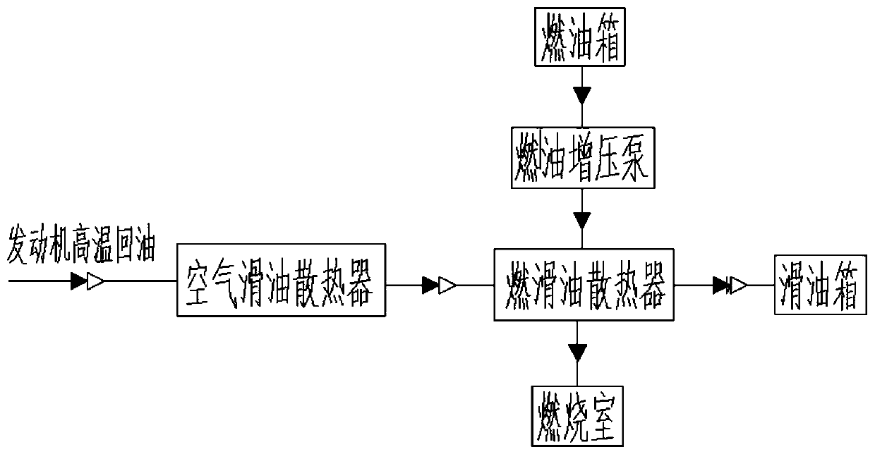
[0026] Such as figure 1 As shown, it is a schematic diagram of the engine lubricating oil cooling system provided by the present invention, and the cooling system includes a lubricating oil tank, an air lubricating oil radiator, a fuel lubricating oil radiator, a fuel tank and a fuel pump;

[0027] The high-temperature return oil of the engine passes through the air lubricating oil radiator and then enters the fuel lubricating oil radiator for heat dissipation, and then enters the lubricating oil tank for recycling;

[0028] The high-temperature fuel in the fuel tank is input to the fuel oil radiator through the fuel pump to dissipate heat, and then input to the combustion chamber through the main fuel pump for combustion.

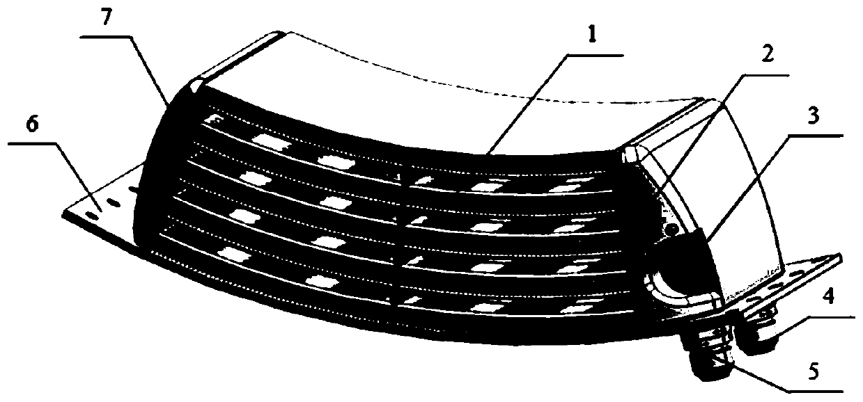
[0029] Such as figure 2 Shown is a schematic structural diagram of the air oil radiator, which includes a core body 1, a front cover 2, a bypass val...


PUM


Abstract

The invention provides an engine lubricating oil cooling system which is composed of a lubricating oil tank, an air lubricating oil radiator, a fuel-lubricating oil radiator, a fuel tank and a fuel pump. High-temperature return lubricating oil of an engine enters the fuel-lubricating oil radiator for heat dissipation after passes through the air lubricating oil radiator, and then enters the lubricating oil tank for recycling; and low temperature fuel in the fuel tank is input to the fuel-lubricating oil radiator through the fuel pump to dissipate the heat of lubricating oil, and then enters acombustion chamber for combustion. The engine lubricating oil cooling system uses two types of radiators to cool the lubricating oil, and the problem that the fuel flow of a high-altitude cruise-typeaviation engine in a high-altitude low-speed state is small and the heat dissipation of the lubricating oil system cannot be met are solved.

Description

technical field [0001] The invention relates to the field of aero-engines, in particular to an aero-engine lubricating oil cooling system. Background technique [0002] During the working process of the aviation engine lubricating oil system, the lubricating oil cools the engine bearings, gears and other parts, and takes away the heat generated by their frictional operation, so that the temperature of the lubricating oil rises. For aero-engines, in order to ensure proper lubricating oil temperature, it is necessary to use low-temperature fuel to cool high-temperature lubricating oil. [0003] However, for high-altitude cruising aero-engines, the fuel flow is very small at high altitude and low speed, which cannot meet the heat dissipation requirements of the lubricating oil, and the design of the lubricating oil cooling system is very difficult. Therefore, the lubricating oil system must find other cooling methods. At present, there are very few technical introductions in ...

Claims


Application Information

Patent Timeline
Patent Type & Authority Applications(China)
IPC IPC(8): F02C7/14F02C7/06F02C7/22F02C7/20
CPCF02C7/06F02C7/14F02C7/20F02C7/22
Inventor 王敏赵强金健李贵林宋飞鄢光荣赵欣周杉
Owner AECC SICHUAN GAS TURBINE RES INST
Why Eureka
Try Eureka