Low-bounce high-speed electromagnetic actuator

An electromagnetic actuator, high-speed technology, applied in electrical control, machine/engine, fuel injection control, etc., can solve the problems affecting the opening or closing timing of the control valve, affecting the working consistency and life, affecting the accuracy of fuel injection control, etc. Achieve the effect of improving switch control accuracy, prolonging service life and improving control accuracy

Active Publication Date: 2020-03-27
CHANGSHA UNIVERSITY OF SCIENCE AND TECHNOLOGY
View PDF6 Cites 1 Cited by
  • Summary
  • Abstract
  • Description
  • Claims
  • Application Information

AI Technical Summary

Problems solved by technology

In order to meet the high-response characteristics of the electronically controlled fuel system, the armature of a conventional high-speed electromagnetic actuator will collide violently with the valve seat or the limit device at a high speed when it is engaged or released, resulting in large rebound and oscillation, which will affect the control. The actual opening or closing time of the valve will affect the control accuracy of fuel injection. At the same time, long-term work will cause damage to the valve seat or limit device, which will affect the consistency and life of its work.

Method used


Image

  • Low-bounce high-speed electromagnetic actuator
  • Low-bounce high-speed electromagnetic actuator
  • Low-bounce high-speed electromagnetic actuator

Examples


Embodiment approach 1

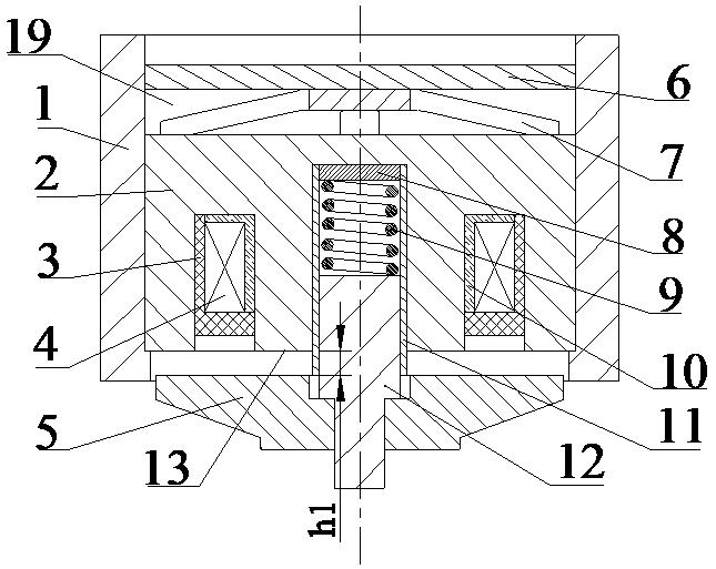
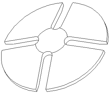
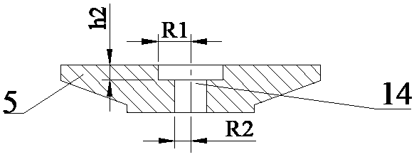
[0019] Embodiment 1: Combining figure 1 , figure 2 , image 3 , Figure 4 and Figure 5 , the composition of this embodiment includes a housing 1, an iron core 2, a sealing resin 3, a coil 4, an armature 5, a fastening nut 6, a disk leaf spring 7, a spring washer 8, a return spring 9, a coil skeleton 10, a guide Set 11 and armature core 12. There is a stepped through hole in the center of the shell 1, and the upper end is tapped with threads, in which the iron core 2, the disc leaf spring 7 and the fastening nut 6 are installed. The iron core 2 is a cylindrical structure of soft magnetic material, with a ring groove on the end surface and a blind hole in the center. The coil 4 is wound on the bobbin 10, arranged in the ring groove of the iron core 2, and sealed by the sealing resin 3. Sealing is performed, and the height of the sealing resin 3 filling the ring groove is lower than the iron core end surface 13, so as to avoid thermal expansion overflowing the ring groove....

Embodiment approach 2

[0021] Embodiment 2: On the basis of Embodiment 1, the plate spring chamber 19 is filled with compressible oil to further quickly attenuate the energy of the collision between the armature 5 and the guide sleeve 11 and reduce the bounce and vibration of the armature core 12 .


PUM


Abstract

The invention provides a low-bounce high-speed electromagnetic actuator. The low-bounce high-speed electromagnetic actuator comprises a shell, an iron core, sealing resin, coils, an armature, a fastening nut, a disc leaf spring, a spring gasket, a return spring, coil frameworks, a guide sleeve, an armature core and a leaf spring chamber, wherein a stepped through hole is formed in the center of the shell, and the iron core, the disc leaf spring and the fastening nut are arranged in the shell; the iron core is of a cylindrical structure, an annular groove is formed in the end face of the iron core, a blind hole is formed in the center of the iron core, each coil is wound on the corresponding coil framework and arranged in an iron core annular groove, the guide sleeve is embedded in the blind hole, and the return spring, the spring gasket and the armature core are installed in the guide sleeve; the armature core is of a cylindrical boss structure, the big end is matched with the guide sleeve, a stepped hole is formed in the center of the armature, and the small end of the armature core is sleeved with an armature sleeve; and the disc leaf spring is of a petal-shaped structure and ispositioned above the iron core, and the disc leaf spring and the iron core are tightly locked in the shell through the fastening nut. The low-bounce high-speed electromagnetic actuator has the advantages of high response, low bounce and long service life, and is suitable for an electric control fuel system of a diesel engine.

Description

technical field [0001] The invention relates to an electromagnetic actuator, in particular to a high-speed electromagnetic actuator for an electronically controlled fuel system of a diesel engine. Background technique [0002] With the development of diesel engine electronic control technology, the electronically controlled fuel injection system has gradually replaced the mechanical fuel injection control system and has become an important technology for diesel engine fuel injection control. At present, diesel engines are facing increasingly stringent emission regulations and lower fuel consumption requirements, and electronic control technology is an important means to meet these requirements. The high-speed electromagnetic actuator is an important component of the electronically controlled fuel injection system of the diesel engine. It can accurately and flexibly control the fuel injection timing, fuel injection quantity and fuel injection law through the opening and closi...

Claims


Application Information

Patent Timeline
Patent Type & Authority Applications(China)
IPC IPC(8): F02M51/06F02M61/16F02D41/20
CPCF02D41/20F02M51/0625F02M61/16
Inventor 刘鹏邓家福盘江强段淑贞李威虢沧岩王伟赫
Owner CHANGSHA UNIVERSITY OF SCIENCE AND TECHNOLOGY
Why Eureka
Try Eureka