
Pneumatic hydraulic safety system

A safety system, pneumatic hydraulic technology, applied in the direction of fluid pressure actuation system safety, fluid pressure actuation device, servo motor, etc., can solve the problems of noise, inability to switch according to needs, energy waste, etc., to reduce noise and energy The effect of waste, good practicability, and smooth air path

Active Publication Date: 2020-03-27
CRRC YANGTZE CO LTD
View PDF6 Cites 1 Cited by
  • Summary
  • Abstract
  • Description
  • Claims
  • Application Information

AI Technical Summary

Problems solved by technology

[0003] Aiming at the deficiencies in the above-mentioned prior art, the present invention provides a pneumatic-hydraulic safety system to solve the technical problems of noise, energy waste and inability to switch according to needs caused by hydraulic cylinders that are always in working condition in the prior art

Method used


Image

  • Pneumatic hydraulic safety system

Examples


Embodiment Construction

[0031] The following will clearly and completely describe the technical solutions in the embodiments of the present invention with reference to the accompanying drawings in the embodiments of the present invention. Obviously, the described embodiments are only some, not all, embodiments of the present invention. Based on the embodiments of the present invention, all other embodiments obtained by persons of ordinary skill in the art without making creative efforts belong to the protection scope of the present invention.

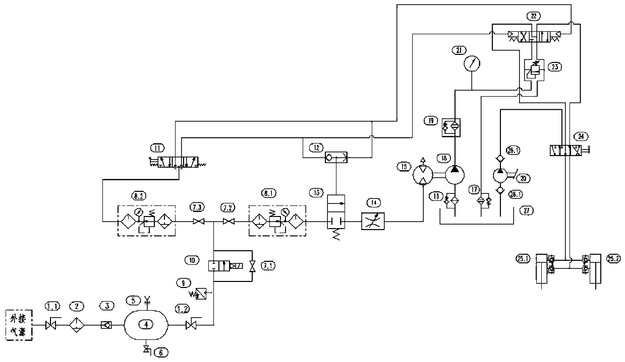
[0032] figure 1 It is a schematic diagram of the hydraulic layout of a pneumatic hydraulic safety system according to an embodiment of the present invention, combined with figure 1, the system includes an air storage tank 4, a pressure switch 9, a two-position two-way switching valve 10, a first three-position five-way reversing valve 11, a shuttle valve 12, a two-position two-way air control valve 13, an air control hydraulic valve 22, a drive Motor 15, hydr...


PUM


Abstract

The invention belongs to the technical field of hydraulic control, and particularly relates to a pneumatic hydraulic safety system. The pneumatic hydraulic safety system comprises an air storage tank,a pressure switch, a two-position two-way switching valve, a first three-position five-way reversing valve, a shuttle valve, a two-position two-way pneumatic control valve, a driving motor, a first hydraulic pump, an oil tank, a pneumatic control hydraulic valve and a hydraulic oil cylinder. According to the pneumatic hydraulic safety system, through the matching of the first three-position five-way reversing valve, the shuttle valve, the two-position two-way pneumatic control valve and the pneumatic control hydraulic valve, the driving motor can be in the stop and start state, thus the expansion and contraction of the hydraulic oil cylinder can be started according to the needs, so that the problems of noise and energy waste can be reduced, the expansion and contraction of the hydraulicoil cylinder can also be switched according to the needs, and good practicability is achieved.

Description

technical field [0001] The invention belongs to the technical field of hydraulic control, in particular to a pneumatic hydraulic safety system. Background technique [0002] In the operation of railway engineering vehicles, the hydraulic cylinder is a relatively practical and mature operating mechanism. The expansion and contraction of the hydraulic cylinder is realized by the movement of the hydraulic oil in its rod chamber and rodless chamber. The hydraulic oil delivered by the rodless cavity is realized by pumping hydraulic oil from the oil tank through the hydraulic pump, and the hydraulic pump is driven by the drive motor. In the prior art, if the control system is not used, the compressed air is directly connected to the drive motor Therefore, the hydraulic pump driven by the drive motor will always be in working condition, and then the expansion and contraction of the hydraulic cylinder will always be in working condition, which causes the problems of noise and energy...

Claims


Application Information

Patent Timeline
IPC IPC(8): F15B11/17F15B13/06F15B20/00
CPCF15B11/17F15B13/06F15B20/004F15B2211/20507F15B2211/255
Inventor 石峰汤楚强何衍眭维涂智文雷青平王丽娜
Owner CRRC YANGTZE CO LTD
Learn More