Damping equipment of motor base

A technology of shock absorption equipment and motor base, which is applied in the direction of mechanical equipment, engine base, spring/shock absorber, etc. It can solve the problems of easy loosening of shock absorbing pads, limited shock absorption effect, loose motor parts, etc., and achieve enhanced shock absorption effect, improved stability, and increased service life

Active Publication Date: 2020-03-27
HUNAN GAOKE ELECTRONICS TECH
View PDF6 Cites 3 Cited by
  • Summary
  • Abstract
  • Description
  • Claims
  • Application Information

AI Technical Summary

Problems solved by technology

However, the motor will vibrate during operation. The long-term and high-frequency vibration of the motor will not only loosen the internal parts of the motor, but also cause the parts of the motor-driven equipment to loosen and fall off, and even cause irreparable consequences.
[0003] The method of installing a shock absorber between the motor and the mounting base is also often used, but the shock absorber is easy to loosen and fall off, and the shock absorbing effect is also limited. Therefore, in view of the above current situation, it is urgent to develop a shock absorber for the motor base , to overcome the deficiencies in current practical applications

Method used


Image

  • Damping equipment of motor base
  • Damping equipment of motor base
  • Damping equipment of motor base

Examples


Embodiment 1

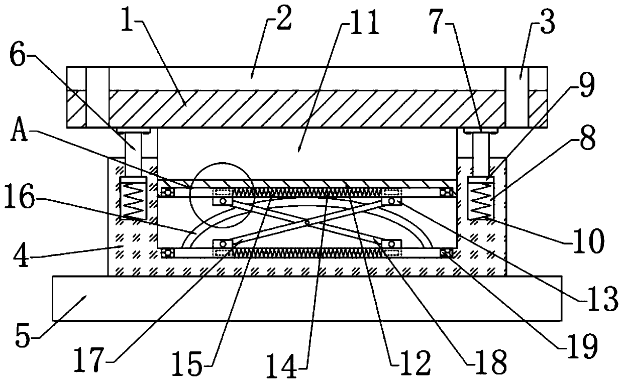
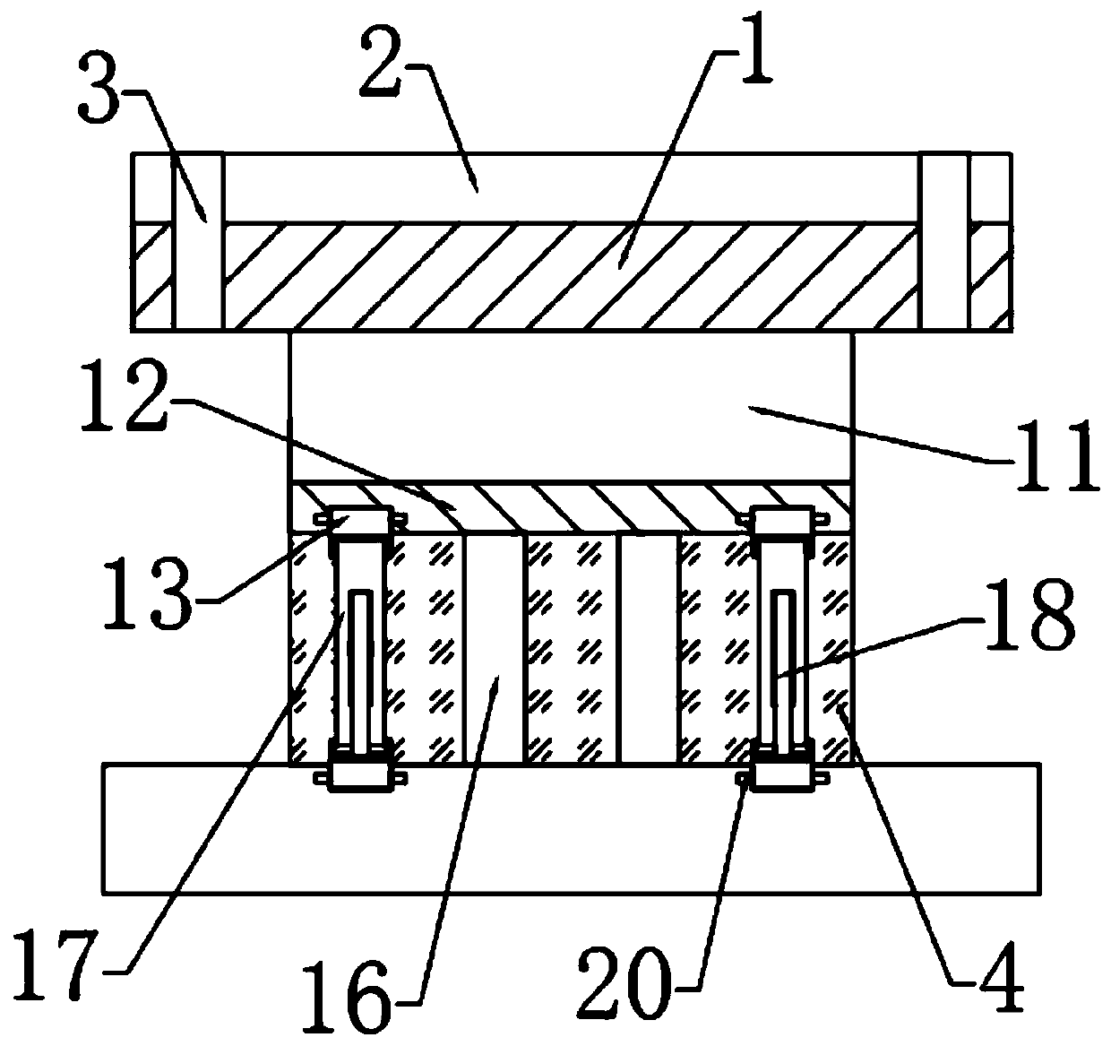
[0026] see Figure 1-4 , in an embodiment of the present invention, a motor base damping device includes a bottom plate 5, the top of the bottom plate 5 is fixedly connected with a fixed block 4, the top of the fixed block 4 is provided with a groove, and the inner side of the groove is slidably connected A bump 11 is provided, the top of the bump 11 is fixedly connected with a mounting plate 1, the top of the mounting plate 1 is provided with a shock absorber 2, and the mounting plate 1 is provided with a number of mounting holes 3, the bump The bottom of 11 is provided with a buffer mechanism, and the left and right ends of the fixed block 4 are provided with connection mechanisms for connecting the mounting plate 1 and the fixed block 4 .

Embodiment 2

[0028] In this embodiment, the buffer mechanism includes a support plate 12, the support plate 12 is arranged on the lower side of the protrusion 11, the support plate 12 is slidably connected with the fixed block 4, the bottom end of the support plate 12 and the top end of the groove The front and rear sides are all provided with a chute 15, and two sliders 13 are slidably connected in the chute 15, and a second spring 14 is fixedly connected between the two sliders 13, and the slider 13 on the upper and lower sides Connected by the first connecting rod 17 and the second connecting rod 18 arranged crosswise, the first connecting rod 11 and the second connecting rod 18 are hinged with the slider 13, and the first connecting rod 17 is connected with the second connecting rod The middle part of the rod 18 is hinged, and a number of elastic metal sheets 16 fixedly connected to the support plate 12 are arranged between the chute 15 on the front and rear sides. By setting a buffer m...


PUM


Abstract

The invention relates to the field of industrial machines, in particular to damping equipment of a motor base. The damping equipment comprises a bottom plate. The top of the bottom plate is fixedly connected with a fixing block, a groove is formed in the top end of the fixing block, the inner side of the groove is slidingly connected with a convex block, the top of the convex block is fixedly connected with a mounting plate, a damping cushion is arranged on the top of the mounting plate, a buffer mechanism is arranged at the bottom of the convex block, and connecting mechanisms for connectingthe mounting plate and the fixing block are arranged at the left end and the right end of the fixing block. As the buffer mechanism is arranged, vibration force caused by a motor can be effectively relieved, the problem that the vibration force generated when the motor runs is very serious is solved, and the service life of the motor and a mounting seat is prolonged; as the connecting mechanisms are arranged, the device is conveniently mounted, and meanwhile, as first springs are arranged, the damping effect of the device can be enhanced; and as the damping cushion is arranged, due to the composite structure of metal and rubber, the strength and the damping capacity of the damping cushion are enhanced.

Description

technical field [0001] The invention relates to the field of industrial machinery, in particular to a shock absorbing device for a motor base. Background technique [0002] The motor is a device that converts electrical energy into mechanical energy. At present, most motors are fixed by motor brackets, which are directly fixed by bolt connections. However, the motor will vibrate during operation. The long-term and high-frequency vibration of the motor will not only loosen the internal parts of the motor, but also cause the parts of the motor-driven equipment to loosen and fall off, and even cause irreparable consequences. [0003] The method of installing a shock absorber between the motor and the mounting base is also often used, but the shock absorber is easy to loosen and fall off, and the shock absorbing effect is also limited. Therefore, in view of the above current situation, it is urgent to develop a shock absorber for the motor base , to overcome the deficiencies in...

Claims


Application Information

Patent Timeline
IPC IPC(8): F16M5/00F16F15/08
CPCF16F15/085F16M5/00
Inventor 王贤勇许磊范绍成林宝丽张欣欣杨志娟
Owner HUNAN GAOKE ELECTRONICS TECH
Why Eureka
Try Eureka