Automatic dehumidifying device for dam extension line gauge

A technology of wire drawing instrument and wire drawing, which is applied in the direction of heating device, drying gas arrangement, dryer, etc., which can solve the problems of reducing the measurement accuracy of sensors, poor ventilation, and the inability to fundamentally solve the stability problems of wire drawing equipment, etc. problems, to achieve the effect of reducing the workload of manual maintenance, reducing equipment maintenance costs, and improving the environment inside the protection box

Inactive Publication Date: 2020-03-27
STATE GRID FUJIAN ELECTRIC POWER CO LTD +1
View PDF6 Cites 1 Cited by
  • Summary
  • Abstract
  • Description
  • Claims
  • Application Information

AI Technical Summary

Problems solved by technology

The extension line equipment has a wide range of layout, but the working environment is often relatively harsh, especially the extension line at the top of the dam, which is generally buried under the asphalt concrete road surface, and the ventilation is not smooth, so that the extension line equipment is in a humid environment for a long time. Affect the liquid level of the floating device at the tension line measuring point, reduce the measurement accuracy of the sensor, and reduce the insulation performance of the cable
The existing processing method is to check the liquid level of the floating device at all drawing line measuring points and the conditions in the equipment protection box during daily inspections. This method cannot fundamentally solve the problem of the stability of the drawing line equipment, and it is labor-intensive

Method used


Image

  • Automatic dehumidifying device for dam extension line gauge

Examples


Embodiment Construction

[0011] In order to make the features and advantages of this patent more obvious and easy to understand, the following special examples are described in detail as follows:

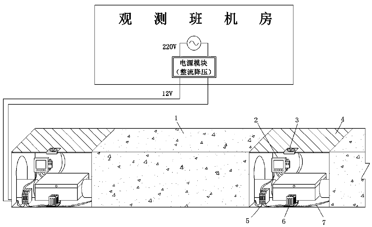
[0012] Such as figure 1 As shown, in the scheme provided in this embodiment: the tension line equipment is buried under the concrete surface 1, and a plurality of measuring points are arranged along the extension direction of the tension line, each measuring point is arranged in a protection box, and the top cover of the protection box 4 is flush with the concrete surface 1; a DC fan 3 is installed on the top cover 4 of the protection box; a DC heater 6 is installed at the bottom of the protection box; a temperature and humidity controller 2 is installed in the protection box; a DC fan 3 and a DC heater 6 The temperature and humidity controller 2 is connected separately. Compared with the temperature and humidity sensor, the temperature and humidity controller 2 can monitor the ambient temperature and humid...


PUM


Abstract

The invention provides an automatic dehumidifying device for a dam extension line gauge. The automatic dehumidifying device for the dam extension line gauge is characterized in that extension line equipment is buried under the concrete surface, a plurality of measuring points are distributed along the extension direction of the extension line, each measuring point is arranged in a protection box,and a top cover of each protection box is flush with the concrete surface; direct-current fans are mounted on the top covers of the protection boxes; the bottom of each protection box is provided witha direct-current heater; a temperature and humidity controller is arranged in each protection box; the direct-current fans and the direct-current heaters are respectively connected with the temperature and humidity controllers; and the temperature and humidity controllers control the direct-current fans and/or the direct-current heaters to start or stop working according to the detected temperature value and humidity value in the protection boxes and a preset temperature threshold value and humidity threshold value. The environment in the extension line protection boxes can be effectively improved, the environment in the protection boxes can be maintained in a good condition for a long time, the reliability of measurement data is improved, the maintenance cost of equipment is reduced, theworkload of manual maintenance is reduced, and high practical popularization value is achieved.

Description

technical field [0001] The invention belongs to the field of routine maintenance of hydroelectric power stations, and in particular relates to an automatic dehumidification device for a dam tensioner. Background technique [0002] Tension line observation is one of the important means of dam horizontal displacement observation. The extension line equipment has a wide range of layout, but the working environment is often relatively harsh, especially the extension line at the top of the dam, which is generally buried under the asphalt concrete road surface, and the ventilation is not smooth, so that the extension line equipment is in a humid environment for a long time. Affect the liquid level of the floating device at the tension line measuring point, reduce the measurement accuracy of the sensor, and reduce the insulation performance of the cable. The existing processing method is to check the liquid level of the floating device at all drawing line measuring points and the ...

Claims


Application Information

Patent Timeline
Patent Type & Authority Applications(China)
IPC IPC(8): F26B21/00F26B23/04
CPCF26B21/004F26B23/04
Inventor 吴雅燕黄鑫林勘尘黄秋萍周振辉连远林敏洁钟闽建
Owner STATE GRID FUJIAN ELECTRIC POWER CO LTD
Why Eureka
Try Eureka