
Eureka
For R&D, Eureka makes reading and utilizing patents & technical documents easy.
Eureka AIR
Designed for self-driven R&D workflows. Generate viable solutions, solve complex R&D challenges, empower your innovation with AI.

Eureka Materials
Designed for material experts only. Revolutionize your material R&D, from search, analyze, to developing new materials.

TechResearch
Generate reliable direction feasibility study reports for your R&D in just a few steps.

TechSeek
Discover and master advanced knowledge NOW. Basics, ideas, possibilities, all at once.

TechMind
As an expert in R&D Theories, TechMind can generates customized viable solutions instantly.

TechRisk
Analyze your overall solution with one click, know your potential R&D risks in advance.

TechMonitor
Get weekly tech updates, stay abreast of the latest tech innovations and key insights.
Plastic ejection mechanism of grain forming machine
A technology of ejection mechanism and molding machine, which is applied in the direction of weapon types, offensive equipment, pyrotechnics, etc., and can solve the problems of easy damage and waste of manpower in the process of pulling out the powder column
- Summary
- Abstract
- Description
- Claims
- Application Information
AI Technical Summary
Problems solved by technology
Method used
Image

Examples
Embodiment 1
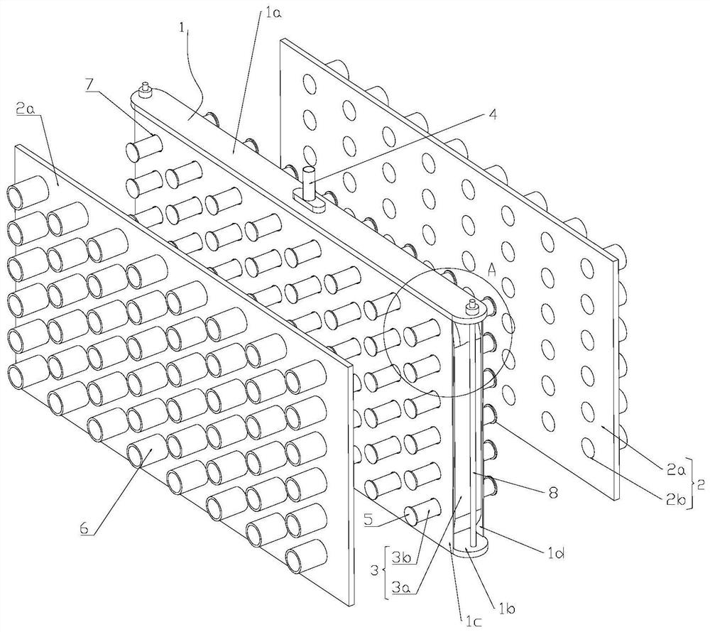
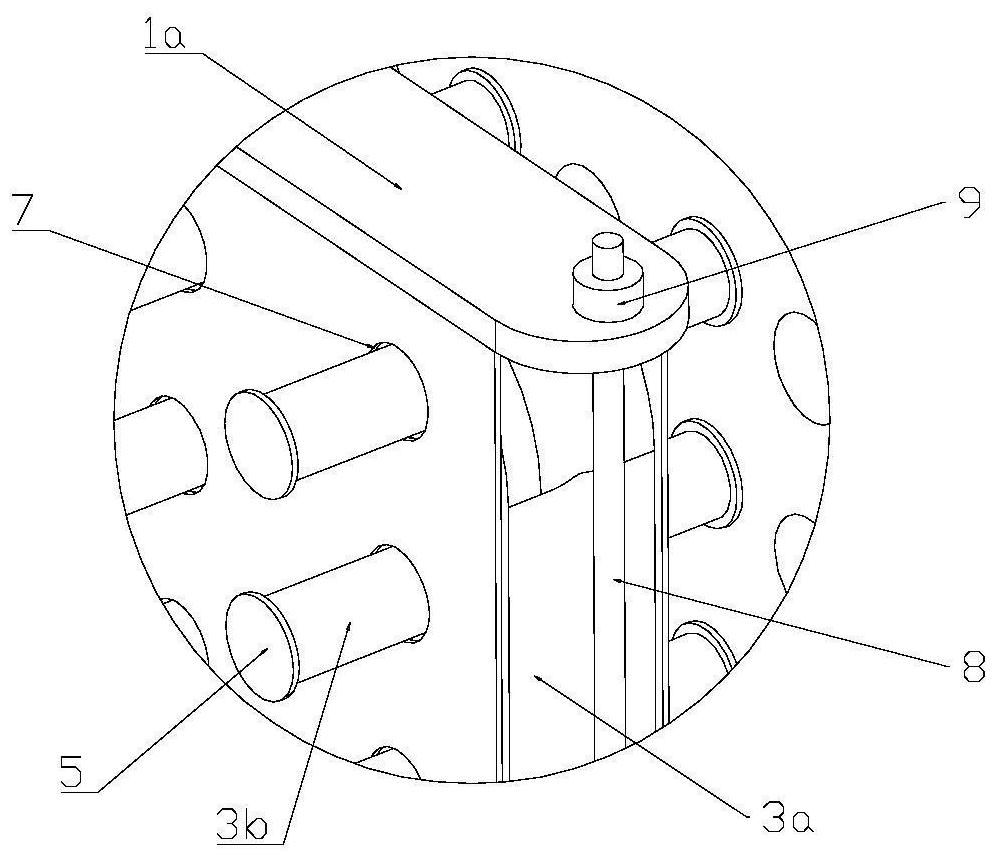
[0018] see figure 1 , figure 2 As shown, the present invention provides a shaping and ejecting mechanism of a grain forming machine, comprising an airbag frame 1 and a shaping plate 2, an inflatable airbag 3 is placed in the airbag frame 1, and a communicating airbag is installed on the airbag frame 1 The air delivery tube 4 of 3, the air delivery tube 4 is externally connected to the air pump, the air bag 3 includes a main air bag 3a and a plurality of branch air bags 3b communicated with the main air bag 3a, the end of the branch air bag 3b is provided with a top sheet 5; the shaping plate 2 includes a shaping The splint 2a, the shaping splint 2a is provided with a plurality of limit holes 2b for the extension of the airbag 3b, the limit hole 2b is coaxially provided with a shaping tube 6, and the top sheet 5 is slidably installed on the shaping tube 6 Inside.
[0019] Specifically, the shaping splint 2a is used to shape the pyrotechnic powder into a powder column. When i...
Embodiment 2
[0022] In this embodiment, one of the optimized designs is made on the basis of the above-mentioned embodiments. The airbag frame 1 includes a top plate 1a and a bottom plate 1b which are opposite and spaced apart, and a front side plate 1c and a front side plate 1c are arranged opposite and spaced between the top plate 1a and the bottom plate 1b. The rear side plate 1d, the air bag 3 is placed in the gap between the top plate 1a, the bottom plate 1b, the front side plate 1c and the rear side plate 1d, the air pipe 4 is installed on the top plate 1a, and both the front side plate 1c and the rear side plate 1d A through hole 7 for extending the branch air bag 3b is provided, and the diameter of the top sheet 5 is larger than the diameter of the through hole 7 . The airbag frame 1 forms a square frame, which can withstand the extrusion of the shaping plate 2 and protect the inner airbag 3 .
[0023] As another improvement, the end of the top plate 1a and the end of the bottom pl...
Embodiment 3
[0025] In this embodiment, one of the optimized designs is made on the basis of the above-mentioned embodiments. There are two plastic splints 2a, one of which is set close to the front side plate 1c, and the other plastic splint 2a is close to the rear Side panel 1d set. Wherein, by arranging the shaping plate 2 in two directions, the grain column can be processed in two directions at the same time, and the processing efficiency can be fully improved.
PUM
 Abstract
Description
Claims
Application Information
 - R&D Engineer
- R&D Manager
- IP Professional
- Industry Leading Data Capabilities
- Powerful AI technology
- Patent DNA Extraction
Browse by: Latest US Patents, China's latest patents, Technical Efficacy Thesaurus, Application Domain, Technology Topic, Popular Technical Reports.
© 2024 PatSnap. All rights reserved.Legal|Privacy policy|Modern Slavery Act Transparency Statement|Sitemap|About US| Contact US: help@patsnap.com