Projection lens
A projection lens and image magnification technology, which is applied in the field of projection lenses, can solve the problems of impracticality and cost increase, and achieve the effect of suppressing optical focus changes
- Summary
- Abstract
- Description
- Claims
- Application Information
AI Technical Summary
Problems solved by technology
Method used
Image
Examples
Embodiment approach 1
[0038] Next, a projection lens according to Embodiment 1 of the present invention will be described with reference to the drawings.
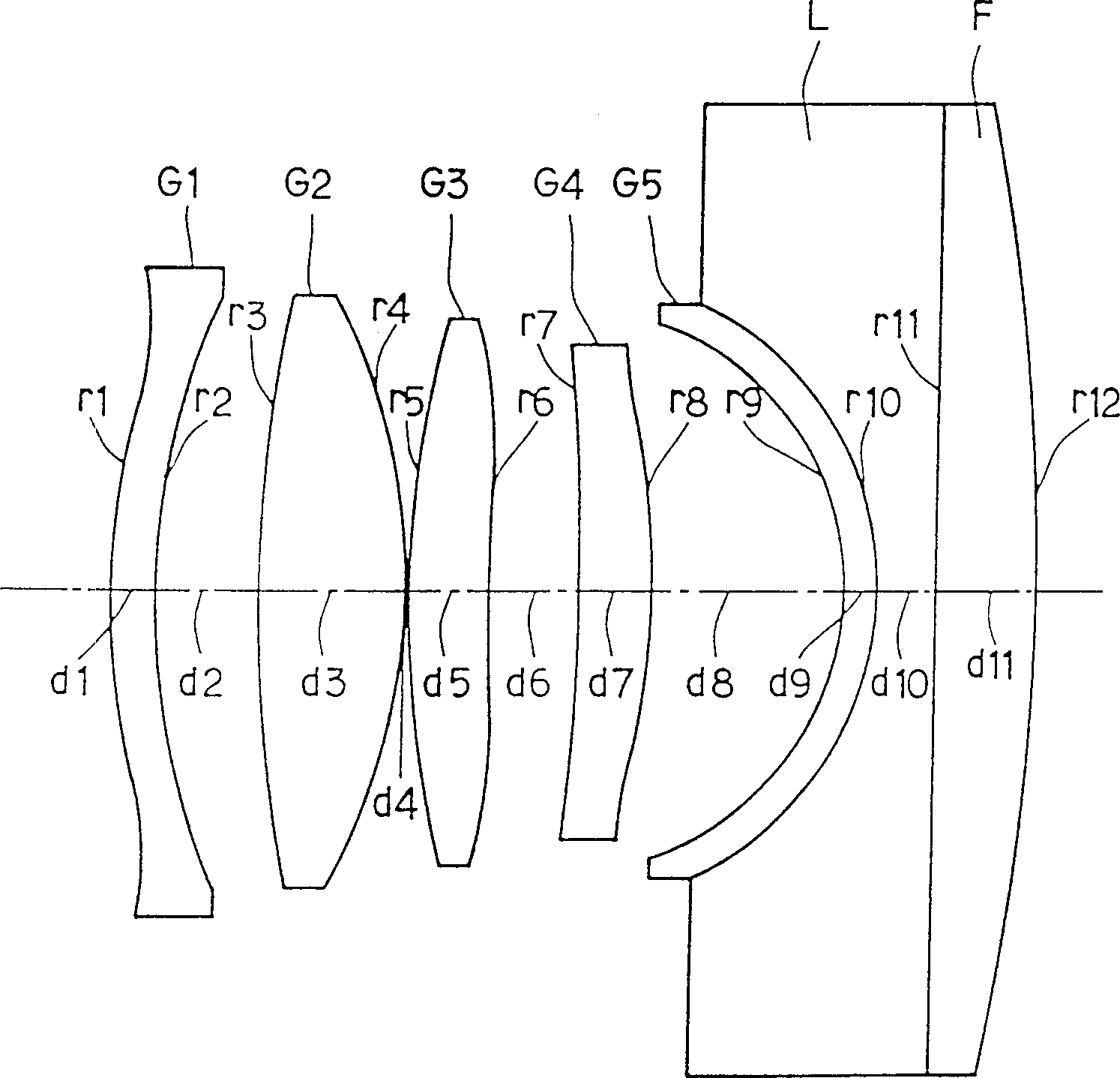
[0039] figure 1 , Figure 5 and Figure 7 The projection lens configuration diagrams of Example 1, Example 2, and Example 3 of Embodiment 1 are in order. According to the projection lens described in the first aspect of the present invention, the lenses from the first group to the fourth group are lenses of positive magnification, the second group has the largest positive magnification in the whole system, and the fourth group has the second largest positive magnification. big lens. The fifth lens group is a negative magnification lens with a concave surface facing the screen side, which mainly corrects image curvature. The first group of lenses and the third group of lenses have the main function of correcting spherical aberration and coma aberration, the second group of lenses undertakes a considerable part of the positive magnification of...
Embodiment 1
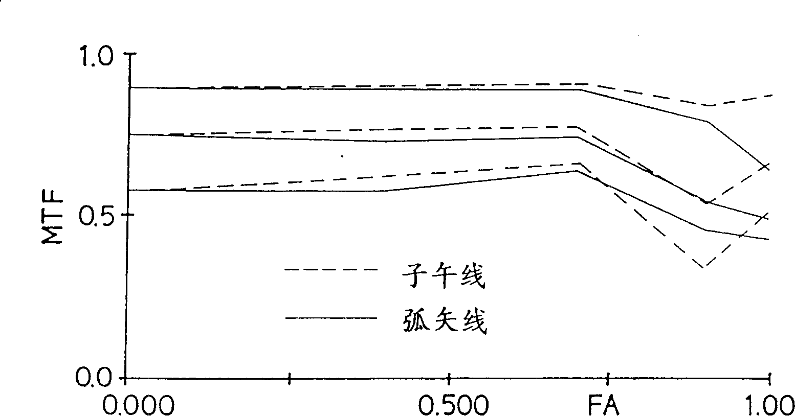
[0048] figure 1 It is a configuration diagram of a projection lens of Example 1 of Embodiment 1. This embodiment 1 is in F NO =1.1, focal length f0=77.6, magnification=9.2, half screen angle of view=39 ° in the projection lens, satisfying the condition of claim 1 will make the optical performance (MTF) good, even if the temperature of the optical coupling liquid of the 5th group From 20°C to 66°C, the change in back focus distance is also within 0.05mm, and this is an example of designing with the aim of setting the distortion aberration within 6%.
[0049] exist figure 1 Among them, the first group lens G1, the third group lens G3, the fourth group lens G4 and the shell lens G5 of the fifth group lens are all acrylic resin plastic lenses, and the second group lens G2 is a SK5 glass lens. The filling material L between the CRT fluorescent screen F and the fifth group of shell lenses G5 uses the optical coupling fluid already mentioned, in order to prevent the contrast betwe...
Embodiment 2
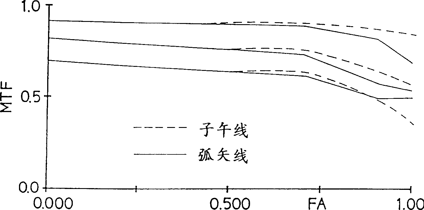
[0097] Figure 5 It is a configuration diagram of a projection lens of Example 2 of Embodiment 1 of the present invention. Embodiment 2 As for Embodiment 1, only the surface spacing between the fourth group and the fifth group, especially the effective aperture and the surface interval outside the effective aperture are enlarged. In this way, although the focus adjustment of the projection lens of the present invention is carried out by moving the first group to the fourth group relative to the fifth group, when the finished product is that the surface interval between the fourth group and the fifth group is narrow, it is due to the When the lens barrel on the 4th group side interferes with the structure on the 5th group side. Especially in the case of high magnification use, compared to the case of low magnification use, the plane interval between the 4th group and the 5th group is narrowed, and phase interference is likely to occur, so it is enlarged compared to Example 1. ...
PUM
 Abstract
Description
Claims
Application Information
 - R&D
- Intellectual Property
- Life Sciences
- Materials
- Tech Scout
- Unparalleled Data Quality
- Higher Quality Content
- 60% Fewer Hallucinations
Browse by: Latest US Patents, China's latest patents, Technical Efficacy Thesaurus, Application Domain, Technology Topic, Popular Technical Reports.
© 2025 PatSnap. All rights reserved.Legal|Privacy policy|Modern Slavery Act Transparency Statement|Sitemap|About US| Contact US: help@patsnap.com


