Optical radiation sensor angle response characteristic testing device

A response characteristic and testing device technology, applied in the field of optical radiation sensor angle response characteristic testing devices, can solve the problems of large volume and power consumption, long light source warm-up time, etc., achieve short warm-up time, low power consumption, and improve detection The effect of efficiency

A response characteristic and testing device technology, applied in the field of optical radiation sensor angle response characteristic testing devices, can solve the problems of large volume and power consumption, long light source warm-up time, etc., achieve short warm-up time, low power consumption, and improve detection The effect of efficiency

CN110926601AActive Publication Date: 2020-03-27航天新气象科技有限公司

Image

  • Optical radiation sensor angle response characteristic testing device
  • Optical radiation sensor angle response characteristic testing device
  • Optical radiation sensor angle response characteristic testing device

Examples


Embodiment 1

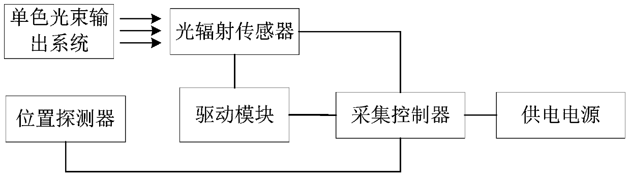
[0031] An embodiment of the present invention provides a device for testing the angular response characteristics of an optical radiation sensor, which is used to test the angular response characteristics of an optical radiation sensor, such as figure 1 As shown, the test device includes: a monochromatic beam output system, an optical radiation sensor, a position detector, an acquisition controller, a drive module, and a power supply, wherein the monochromatic beam output system is used to output a uniform and collimated monochromatic beam; The optical radiation sensor receives the monochromatic light beam and generates an optical response signal; the position detector detects the position of the optical radiation sensor to generate a position signal; the driving module drives the optical radiation sensor and the position detector to perform multi-angle rotation; the acquisition controller collects The optical response signal and the position signal, and generate the test result...


PUM


Abstract

The invention discloses an optical radiation sensor angle response characteristic testing device, which comprises a monochromatic light beam output system, an optical radiation sensor, a position detector, an collection controller, a driving module and a power supply, and is characterized in that the monochromatic light beam output system is used for outputting a uniformly collimated monochromaticlight beam; the optical radiation sensor receives the monochromatic light beam and generates an optical response signal; the position detector detects the position of the optical radiation sensor andgenerates a position signal; the driving module drives the optical radiation sensor and the position detector to rotate at multiple angles; the collection controller acquires the light response signal and the position signal, and generates an optical radiation sensor angle response characteristic test result according to the light response signal and the position signal; the power supply is usedfor supplying power to the optical radiation sensor, the position detector, the collection controller and the driving module. The laser light source is adopted to replace a traditional broadband lightsource, and the device is smaller in size, lower in power consumption, short in preheating time and low in cost.

Description


Claims


Application Information

Patent Timeline
27 Mar 2020
Publication
CN110926601A