Anemograph adjusting device and method and electronic equipment

An anemometer and adjustment technology, which is used in measurement devices, testing/calibration of speed/acceleration/impact measurement equipment, instruments, etc., can solve problems such as low efficiency, cumbersome process, and many input parameters, so as to reduce dependence Effect

Active Publication Date: 2020-03-27
SHANGHAI NANHUA ELECTRONICS
View PDF9 Cites 1 Cited by
  • Summary
  • Abstract
  • Description
  • Claims
  • Application Information

AI Technical Summary

Problems solved by technology

However, during calibration and calibration, it is necessary to manually enter the detection data into the adjusted anemometer, and there are many parameters entered, the process is cumbersome, resulting in low efficiency and prone to errors

Method used


Image

  • Anemograph adjusting device and method and electronic equipment
  • Anemograph adjusting device and method and electronic equipment
  • Anemograph adjusting device and method and electronic equipment

Examples


Embodiment 1

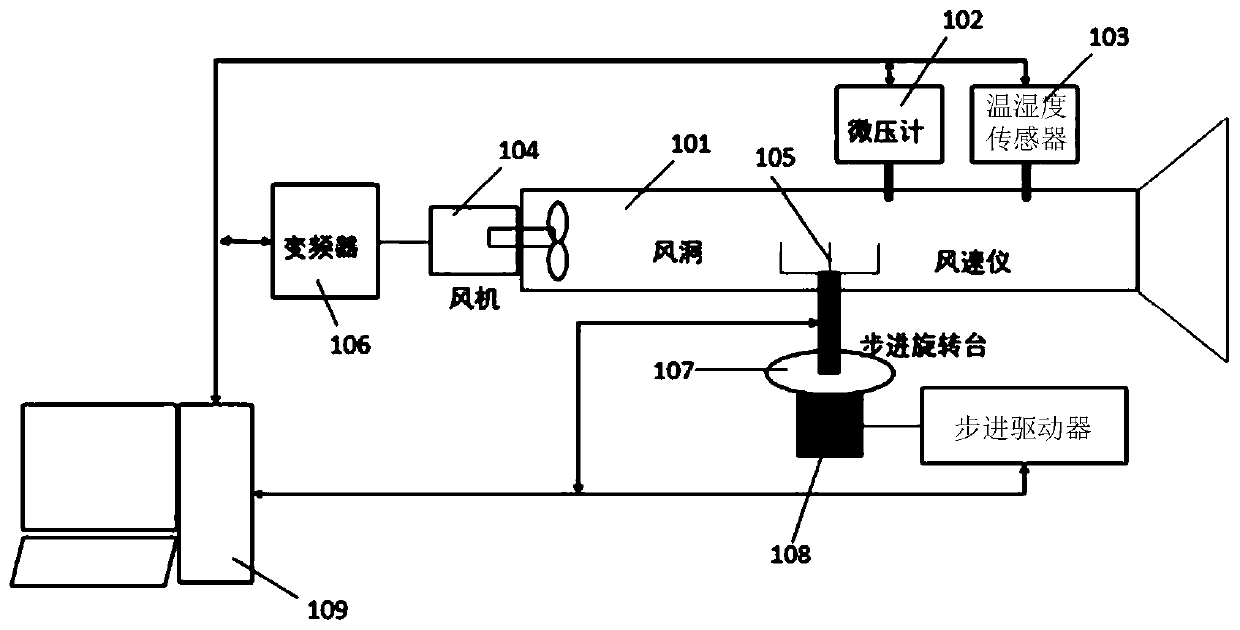
[0056] refer to figure 1 A schematic diagram of an anemometer calibration device is shown, including a wind tunnel 101, a micromanometer 102, a temperature and humidity sensor 103, a fan 104, and an anemometer 105 arranged inside the wind tunnel 101; the fan 104 is also connected to a frequency converter 106 Anemometer 105 also links to each other with stepping turntable 107, and stepping turntable 107 is provided with stepper motor and step driver 108 that are connected; Anemometer 105, micromanometer 102, temperature and humidity sensor 103, frequency converter 106 and The stepper drivers 108 are all connected with the controller 109 .

[0057] Wherein, the stepper driver 108 rotates the stepper motor to the coded zero point position according to the zero point command sent by the controller 109 .

[0058] The fan 104 rotates to provide the wind source for the wind tunnel 101 .

[0059] Both the micromanometer 102 and the temperature and humidity sensor 103 are used to obt...

Embodiment 2

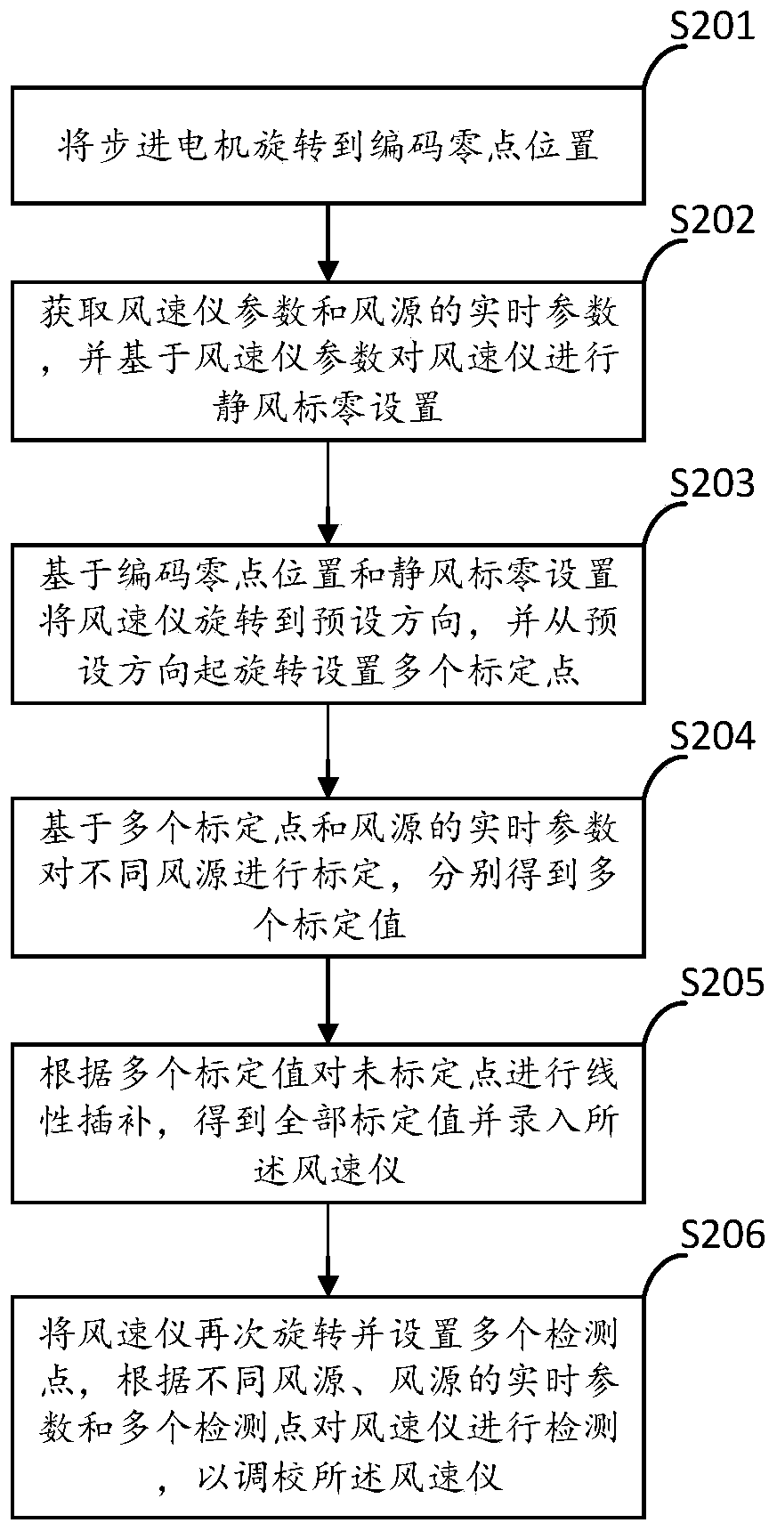
[0071] refer to figure 2 The flowchart of an anemometer calibration method shown can be executed by the controller in the anemometer calibration device of Embodiment 1. The controller can be an electronic device such as a computer or a processor. The method mainly includes steps S201 to S201. S206:

[0072] Step S201, rotating the stepper motor to the code zero position.

[0073] In a specific embodiment, the controller includes but is not limited to a PC, and the PC software sends an instruction to return the stepper motor to absolute zero (ie, the coded zero position). Then install the detected anemometer at a difference of 45 degrees from the horizontal direction. In the end, it is controlled by one key of the PC to realize the fully automatic process of label recording and inspection and report generation. The stepper motor is a stepper motor with integrated encoding, which can read the position signal. The control of the stepper motor is realized by setting the regis...


PUM


Abstract

The invention provides an anemograph adjustment device and method and electronic equipment, and relates to the technical field of anemograph adjustment. The anemograph adjustment device comprises a wind tunnel, and a micromanometer, a temperature and humidity sensor, a fan and an anemograph which are arranged in the wind tunnel; the fan is also connected with the frequency converter; the anemograph is connected with a stepping rotary table, and the stepping rotary table is provided with a stepping motor and a stepping driver which are connected with each other; and the anemograph, the micromanometer, the temperature and humidity sensor, the frequency converter and the stepping driver are all connected with the controller. The stepping driver is used for rotating the stepping motor to a coding zero point position according to a zero point instruction sent by the controller; the fan rotates to provide a wind source for the wind tunnel; the micromanometer and the temperature and humiditysensor are used for acquiring real-time parameters of the air source; the stepping motor controls the anemograph to rotate; and the controller performs static wind indicator zero setting on the anemograph, and performs calibration, linear interpolation and detection on the anemograph based on the encoding zero position and the static wind indicator zero setting so as to adjust the anemograph. Theadjustment and calibration efficiency can be effectively improved, and the error rate can br effectively reduced.

Description

technical field [0001] The invention relates to the technical field of anemometer adjustment, in particular to an anemometer adjustment device, method and electronic equipment. Background technique [0002] In the prior art, it is usually necessary to calibrate and calibrate the anemometer when adjusting it. However, during calibration and calibration, it is necessary to manually enter the detection data into the anemometer to be adjusted, and there are many parameters entered, the process is cumbersome, resulting in low efficiency and prone to errors. Contents of the invention [0003] The object of the present invention is to provide an anemometer calibration device, method and electronic equipment, which can effectively improve the calibration efficiency and reduce the error rate. [0004] In the first aspect, the present invention provides an anemometer calibration device, which includes a wind tunnel, and a micromanometer, a temperature and humidity sensor, a fan and...

Claims


Application Information

Patent Timeline
Patent Type & Authority Applications(China)
IPC IPC(8): G01P21/02
CPCG01P21/025
Inventor 陆洋汪铁保张宾张翔蒋泰
Owner SHANGHAI NANHUA ELECTRONICS
Why Eureka
Try Eureka