Aviation whisk broom photographic device

A photographic device and aviation technology, applied in the field of aerial photography, can solve the problems of heavy workload, high cost, heavy load pressure of aircraft, etc., and achieve the effect of reducing cost and load pressure

Pending Publication Date: 2020-03-27
上海航遥信息技术有限公司
View PDF0 Cites 0 Cited by
  • Summary
  • Abstract
  • Description
  • Claims
  • Application Information

AI Technical Summary

Problems solved by technology

[0003] The present invention provides an aerial swing-sweep photographic device, which aims to improve the existing multi-view aerial photographic devices that use multiple aerial cameras, which have high cost, heavy workload, and cause relatively large load pressure on the aircraft.

Method used


Image

  • Aviation whisk broom photographic device
  • Aviation whisk broom photographic device
  • Aviation whisk broom photographic device

Examples


Embodiment 1

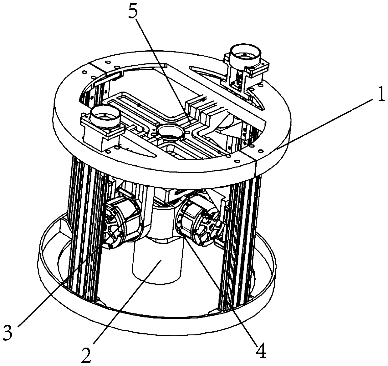
[0027] Please refer to Figure 1-Figure 3 As shown, the present embodiment provides an aerial sweep camera device, which is installed on an aircraft, preferably under the aircraft. In this embodiment, the aircraft may be a drone, a helicopter, or a passenger plane.

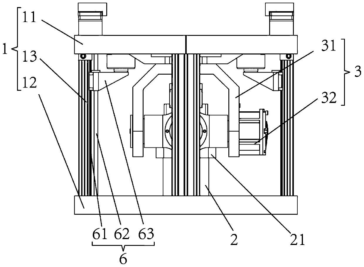
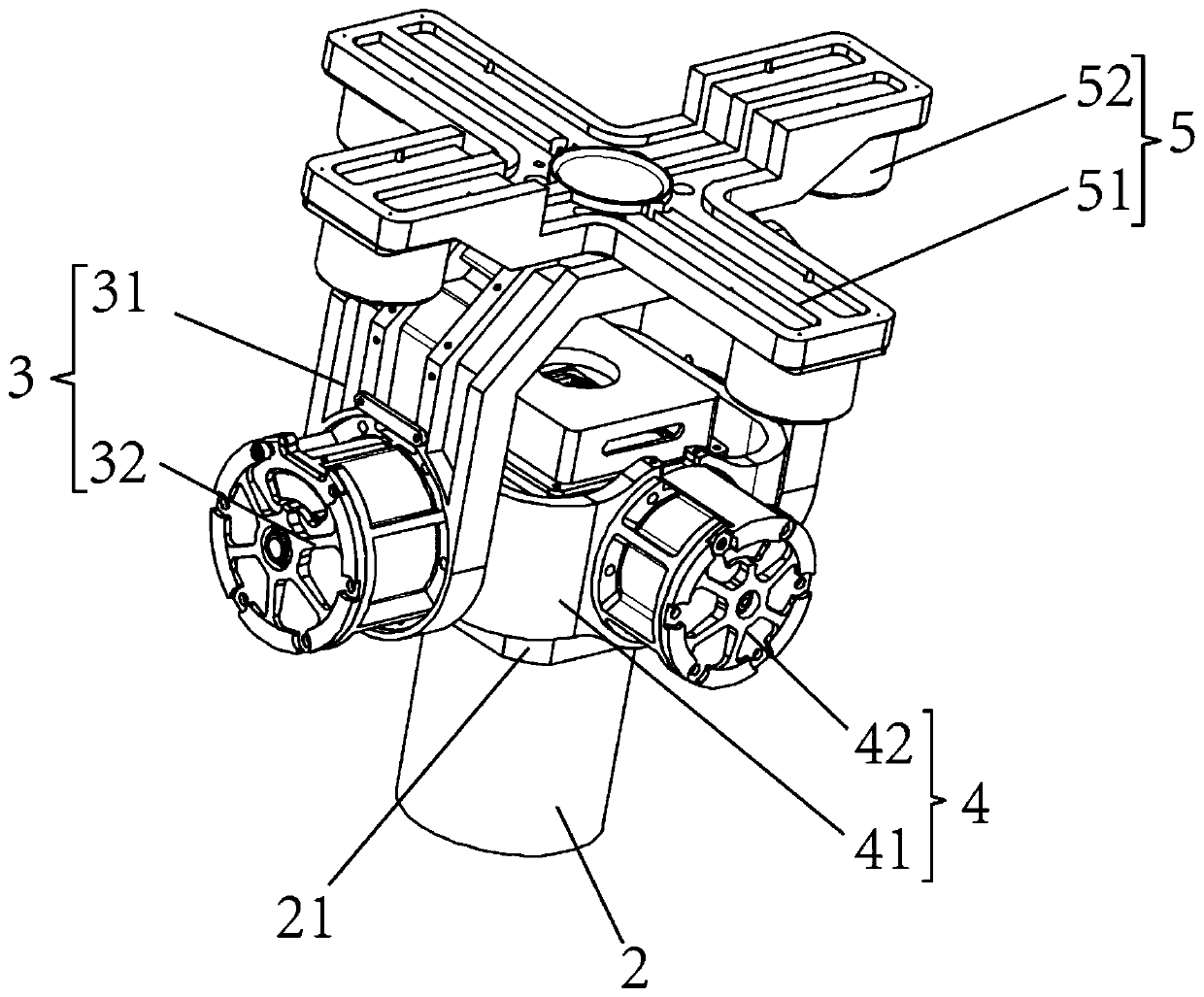
[0028] The aerial sweep camera device comprises: main frame 1, sweep assembly 3 and camera 2, and sweep assembly 3 is arranged on the main frame 1, and main frame 1 is used for being connected with aircraft, and can simultaneously sweep assembly 3 and camera 2 play a protective role. The sweeping assembly 3 is arranged on the main frame 1 , preferably inside the main frame 1 , so that the main frame 1 can protect the sweeping assembly 3 . The camera 2 is arranged on the swing-broom assembly 3 and can swing under the drive of the swing-broom assembly 3 to realize multi-angle shooting. Specifically, the swing assembly 3 drives the camera 2 to swing around the first straight line. At the same time, in order to ma...

Embodiment 2

[0040] The difference between this embodiment and Embodiment 1 is that a lifting assembly 6 is also provided. The lifting assembly 6 is arranged on the main frame 1 , and the swing-sweeping assembly 3 is arranged on the lifting assembly 6 . Meanwhile, the lifting assembly 6 , the swing assembly 3 and the camera 2 are all arranged in the accommodation space of the main frame 1 . That is, the swing assembly 3 is connected to the main frame 1 through the lift assembly 6, and the lift assembly 6 is used to drive the swing assembly 3 to move relative to the main frame 1. Specifically, the lift assembly 6 can drive the swing assembly 3 to and from the storage space. . In this embodiment, the swing-broom assembly 3 is the same as the swing-broom assembly 3 in Embodiment 1. It is worth noting that in this embodiment, the shock absorbing assembly 5 is optional. When the shock absorbing assembly 5 is not provided, the swing sweep assembly 3 is directly connected to the lifting assembl...


PUM


Abstract

The invention provides an aviation whisk-broom photographing device, and relates to the field of aviation photographing. An aviation whisk broom photographing device is arranged on an aircraft, and comprises: a main frame, a whisk broom assembly and a camera, the whisk broom assembly is arranged on the main frame, the camera is arranged on the whisk broom assembly, the main frame is used for beingconnected with the aircraft, and the whisk broom assembly is used for driving the camera to swing in a reciprocating mode. When shooting is carried out, the swing sweeping assembly drives the camerato swing and controls the camera to continuously shoot in the swing process, so that the camera can carry out multi-angle shooting. According to the aviation whisk broom photographing device, multi-angle aviation photographing can be completed only through one camera, and the photographing area of a single air route is increased, so the cost is reduced, and the load pressure of an aircraft is alsoreduced.

Description

technical field [0001] The invention relates to the field of aerial photography, in particular to an aerial swing-broom photography device. Background technique [0002] With the development of computer hardware and software and computer vision technology, people can use digital cameras to take large overlapping pictures of the scene from multiple angles, and use the acquired image data to generate three-dimensional data of the scene through computer production with automatic modeling software . Aerial photography using this technology is called multi-view aerial photography (also called oblique photography), and is widely used in the production of real 3D model data on the ground. Existing multi-view aerial photography devices usually use multiple (generally five or more) aerial cameras placed at different angles (that is, different shooting angles) for shooting, so as to achieve large overlapping shooting from multiple angles. However, due to the high price and large siz...

Claims


Application Information

Patent Timeline
Patent Type & Authority Applications(China)
IPC IPC(8): G03B37/02G03B17/56B64D47/08
CPCG03B37/02G03B17/561B64D47/08
Inventor 王光赵金祥顾耕王燕宁刘亚萍
Owner 上海航遥信息技术有限公司
Why Eureka
Try Eureka