Cable bridge with convenient connection and fireproof function

A cable bridge and bridge technology, applied in the direction of electrical components, etc., can solve the problems of inconvenient cable bridge installation and disassembly, inconvenient cable maintenance, fueling the fire, etc., to achieve the effects of easy laying and replacement, narrowing the scope of fire, and enhancing the effect of fire extinguishing

Active Publication Date: 2020-03-27
青岛邦钲电气集团有限公司
View PDF11 Cites 4 Cited by
  • Summary
  • Abstract
  • Description
  • Claims
  • Application Information

AI Technical Summary

Problems solved by technology

[0003] When the cable tray is in use, it is necessary to connect many bridge units in sequence, and the existing connection method is |: a connecting plate 117 is set at the end of the two bridge units 100, and the two ends of the connecting plate 117 are respectively connected to each other by screws 118. The two bridge units 100 are fixedly connected to improve the connection strength of the cable tray. There are three disadvantages in the above connection method: one is that it is not convenient to install and disassemble the cable tray; the other is that the exposed connecting pl

Method used


Image

  • Cable bridge with convenient connection and fireproof function
  • Cable bridge with convenient connection and fireproof function
  • Cable bridge with convenient connection and fireproof function

Examples


Embodiment

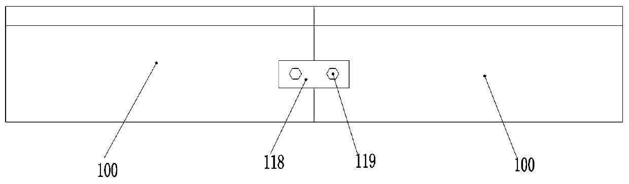
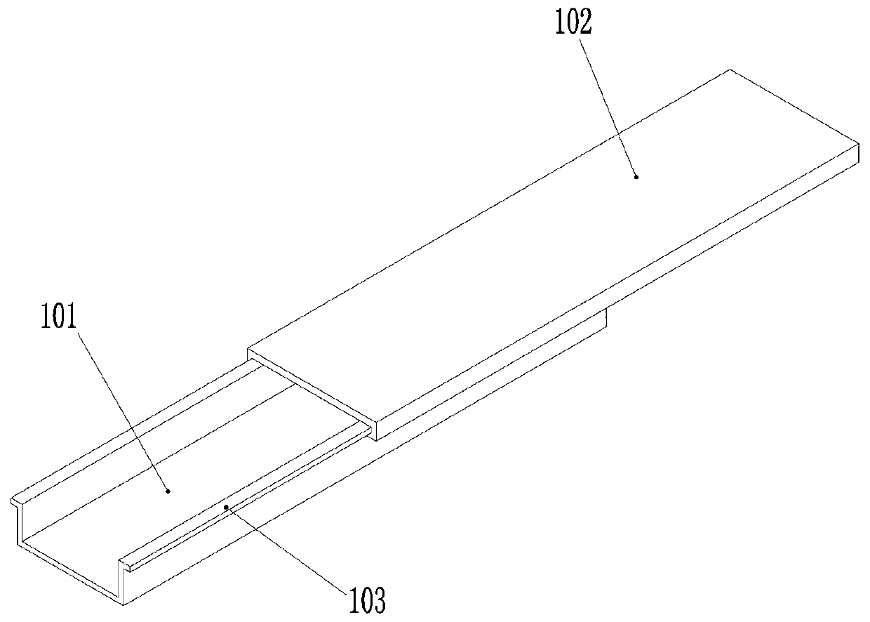
[0030] Example: such as figure 2 , image 3 , Figure 4 As shown, a cable tray with both convenient connection and fire prevention function includes N+1 bridge units 100 connected in sequence, each bridge unit 100 includes a bridge body 101 and a cover plate 102, and the two sides of the bridge body 101 are provided with There are slide rails 103, and slide grooves 104 are provided on both sides of the cover plate 102; the connection mode between two adjacent bridge units 100 is as follows: the cover plate 102 of the Nth bridge unit 100 and the N+1th bridge unit The bridge body 101 of the unit 100 is slidably connected, that is, the right end of the chute 104 on both sides of the N bridge unit 100 is slidably connected with the left end of the slide rail 103 on both sides of the N+1 bridge unit 100; the N bridge unit The bridge body 101 of 100 is slidingly connected with the cover plates 102 of N-1 bridge units 100, that is, the left end of the slide rail 103 on both sides ...


PUM


Abstract

The invention discloses a cable bridge with convenient connection and a fireproof function, and belongs to the technical field of cable bridges. The bridge comprises N + 1 bridge units, each bridge unit comprises a bridge main body and a cover plate, the cover plate of the Nth bridge unit is slidably connected with the bridge main body of the N + 1th bridge unit, and the bridge main body of the Nth bridge unit is slidably connected with the cover plate of the N-1 bridge unit; a fire blocking wall which is perpendicular to the length direction of the bridge frame unit and is provided with a threading hole is inserted into the middle of the bridge frame unit, and an access hole is formed in a bottom plate of the bridge frame unit under the fire blocking wall; a containing cavity is formed inthe top of each bridge unit, through holes used for communicating the containing cavities with inner cavities of the bridge units are formed in the cover plates on the two sides of the fire blockingwall, and hot melt adhesives are arranged in the through holes. According to the cable bridge, the two adjacent bridge units are connected in a sliding mode, so that the whole cable bridge is convenient to mount and dismount quickly, and the fire blocking walls in the inner cavities of the bridge units can effectively prevent fire from flowing.

Description

technical field [0001] The invention relates to the technical field of cable bridges, in particular to a cable bridge with both convenient connection and fire prevention functions. Background technique [0002] Cable tray is a full name of a rigid structural system with close support cables composed of trough-type, tray-type or step-type straight sections, bends, tees, cross components, brackets (arm brackets), hangers, etc. , so as to complete the effect of fixing the cable. [0003] When the cable tray is in use, it is necessary to connect many bridge units in sequence, and the existing connection method is |: a connecting plate 117 is set at the end of the two bridge units 100, and the two ends of the connecting plate 117 are respectively connected to each other by screws 118. The two bridge units 100 are fixedly connected to improve the connection strength of the cable tray. There are three disadvantages in the above connection method: one is that it is not convenient t...

Claims


Application Information

Patent Timeline
IPC IPC(8): H02G3/04
CPCH02G3/0412H02G3/0418
Inventor 不公告发明人
Owner 青岛邦钲电气集团有限公司
Why Eureka
Try Eureka