Duplicate gear riveting method

A duplex gear and riveting technology, which is applied in the field of gears, can solve the problems of large main shaft vibration, uneven edges of the central shaft, burrs, etc., and achieve the effect of small main shaft vibration, smooth appearance and high coaxiality

Active Publication Date: 2020-03-31
贵州华烽汽车零部件有限公司
View PDF6 Cites 3 Cited by
  • Summary
  • Abstract
  • Description
  • Claims
  • Application Information

AI Technical Summary

Problems solved by technology

[0002] Gears are common transmission parts in mechanical equipment or devices. Duplex gears are composed of two gears riveted together side by side. They are generally used in the transmission mechanism of mechanical equipment or devices to transmit different output forces or torques. The quality of the riveting of the double gear has a decisive influence on the reliability of the double gear during operation. In the prior art, when riveting two gears side by side, it is generally completed by a drilling machine, that is, one of the gears is connected to the center set on it. The shaft is fixed on the worktable of the drilling machine, and another gear is fitted side by side on the central shaft, and the corresponding turning riveting head is installed on the main shaft of the drilling machine. The two gears are connected in parallel by flanging along the edge of the shaft. However, in this method in the prior art, since the riveting head rotates with the main shaft of the drilling machine, the precision of the drilling machine itself is low, and the main shaft vibrates greatly during the rotation process. The head is easy to damage the edge of the central axis, and the edge of the central axis is often uneven, with a large number of burrs. Accuracy of transmission mechanism

Method used


Image

  • Duplicate gear riveting method
  • Duplicate gear riveting method

Examples


Embodiment Construction

[0025] The technical solution of the present invention is further described below, but the scope of protection is not limited to the description.

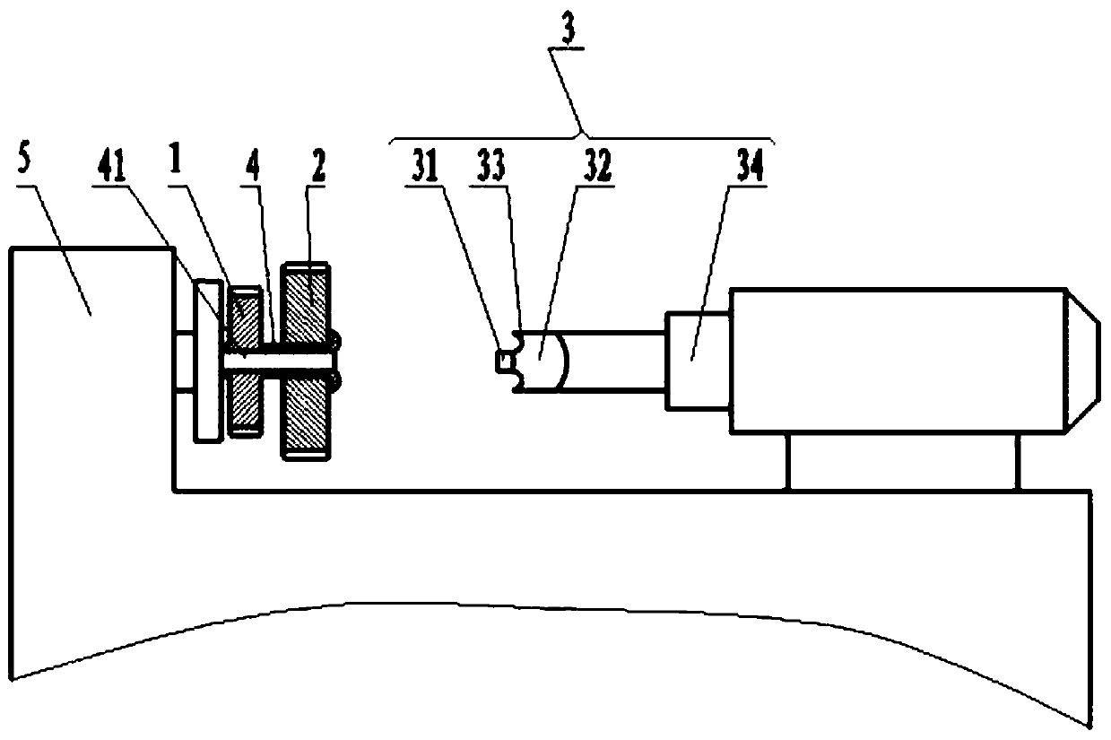
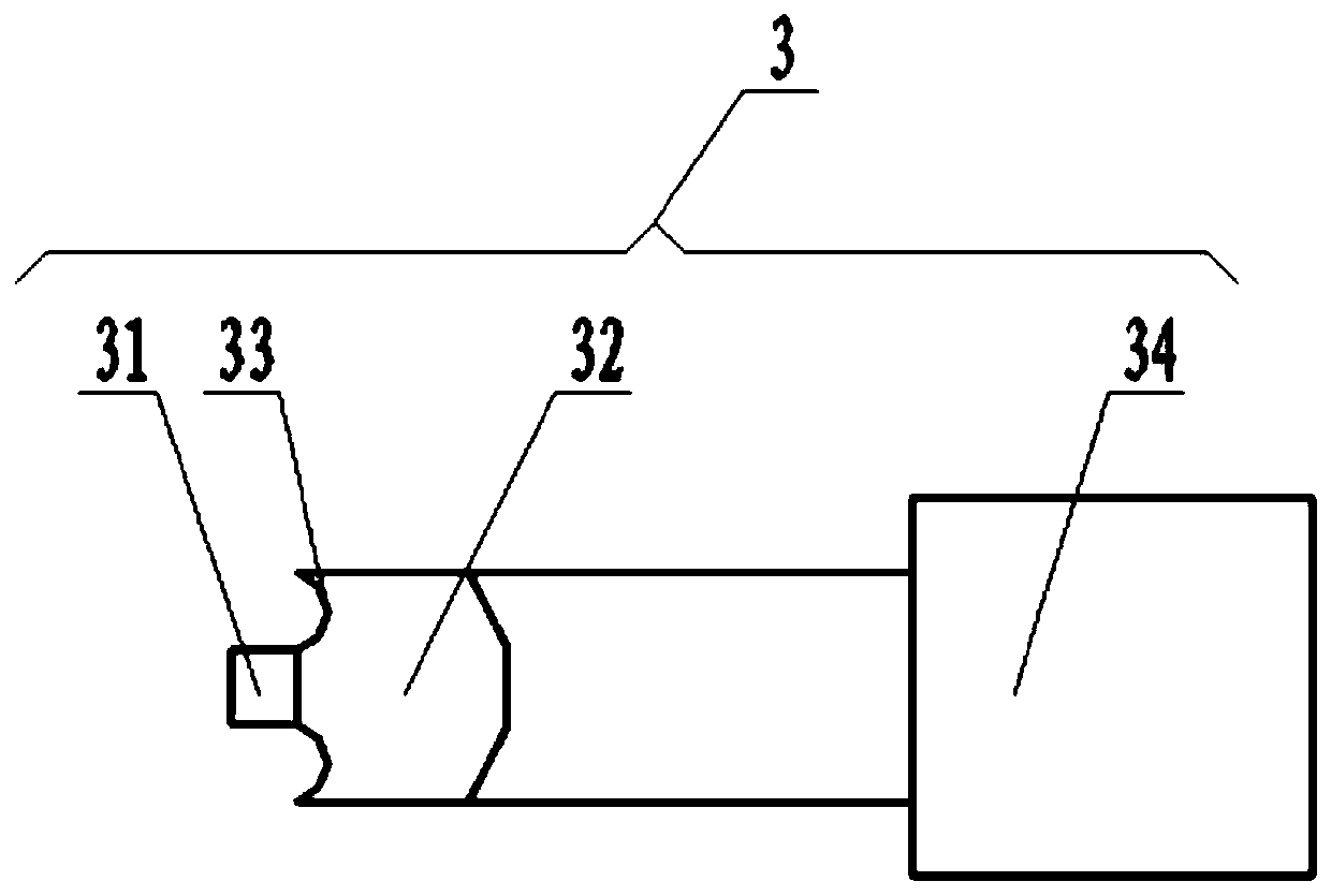
[0026] Such as figure 1 , figure 2 As shown, the present invention provides a double gear riveting method, comprising the following steps:

[0027] Step 1: Provide gear A1, gear B2 and riveting head 3, gear A1 is fixedly connected to the central shaft 4 and the left and right ends of the central shaft 4 extend beyond the left and right sides of the gear A1, and the central shaft 4 is provided with a through The through holes 41 at the left and right ends, and the riveting head 3 include a cylindrical guide post 31;

[0028] Step 2: First clamp one end of the central shaft 4 in step 1 on the main shaft of the lathe 5, and then fix the gear B2 in step 1 to the other end of the central shaft 4;

[0029] Step 3: Start the lathe 5 to rotate the main shaft of the lathe 5. During the rotation of the main shaft of the lathe 5, fit the ...


PUM

PropertyMeasurementUnit
hardnessaaaaaaaaaa
hardnessaaaaaaaaaa
hardnessaaaaaaaaaa

Abstract

The invention provides a duplicate gear riveting method. The method comprises the following steps that a gear A, a gear B and a flanged rivet head are provided, wherein the gear A is fixedly connectedon a central shaft, the left end and the right end of the central shaft extend out of the left side and the right side of the gear A, a middle through hole is formed in the center shaft, and the flanged rivet head comprises a guiding column of a cylinder shape; one end of the central shaft is clamped on a lathe spindle, and then the gear B fixedly sleeves the other end of the central shaft; a lathe is started, the lathe spindle is rotated, the guiding column is sleeved with the middle through hole in the rotating process of the lathe spindle, and the guiding column extrudes the middle throughhole to enable the gear B to be integrally connected with the central shaft so as to obtain a duplicate gear. According to the technical scheme of the method, the influence of the vibration of a machine tool in the riveting process is reduced, the periphery of a flanged rivet rib generated by the deformation of the extruded edge of the central shaft is uniform, so that the firm and reliable effect is achieved, the peripheral rotating inertia is kept balanced, the using effect is improved, and the transmission precision of a transmission mechanism is guaranteed.

Description

technical field [0001] The invention belongs to the technical field of gears, in particular to a double gear riveting method. Background technique [0002] Gears are common transmission parts in mechanical equipment or devices. Duplex gears are composed of two gears riveted together side by side. They are generally used in the transmission mechanism of mechanical equipment or devices to transmit different output forces or torques. The quality of the riveting of the double gear has a decisive influence on the reliability of the double gear during operation. In the prior art, when riveting two gears side by side, it is generally completed by a drilling machine, that is, one of the gears is connected to the center set on it. The shaft is fixed on the worktable of the drilling machine, and another gear is fitted side by side on the central shaft, and the corresponding turning riveting head is installed on the main shaft of the drilling machine. The two gears are connected in pa...

Claims


Application Information

Patent Timeline
Patent Type & Authority Applications(China)
IPC IPC(8): B21D39/00
CPCB21D39/00
Inventor 钱为民彭文利
Owner 贵州华烽汽车零部件有限公司
Why Eureka
Try Eureka