Method for changing water wave propagation direction by arranging underwater obstacle

A technology of propagation direction and obstacles, applied in the field of changing the propagation direction of water waves, can solve the problems of high cost and complicated installation, and achieve the effect of weakening wave intensity, reducing requirements and simple application conditions.

Active Publication Date: 2020-03-31
WUHAN UNIV OF TECH
View PDF5 Cites 4 Cited by
  • Summary
  • Abstract
  • Description
  • Claims
  • Application Information

AI Technical Summary

Problems solved by technology

At present, the monopoly is the fin stabilizer, which has the best anti-roll effect, but the device is complicated and expensive, and it is generally only used for military ships and some ships that require very high anti-roll

Method used


Image

  • Method for changing water wave propagation direction by arranging underwater obstacle
  • Method for changing water wave propagation direction by arranging underwater obstacle
  • Method for changing water wave propagation direction by arranging underwater obstacle

Examples


Embodiment 1

[0039] In the first embodiment, the flow channel is 20 cm wide, 50 cm long, 5 cm deep, and the incident water wave frequency is 20 Hz.

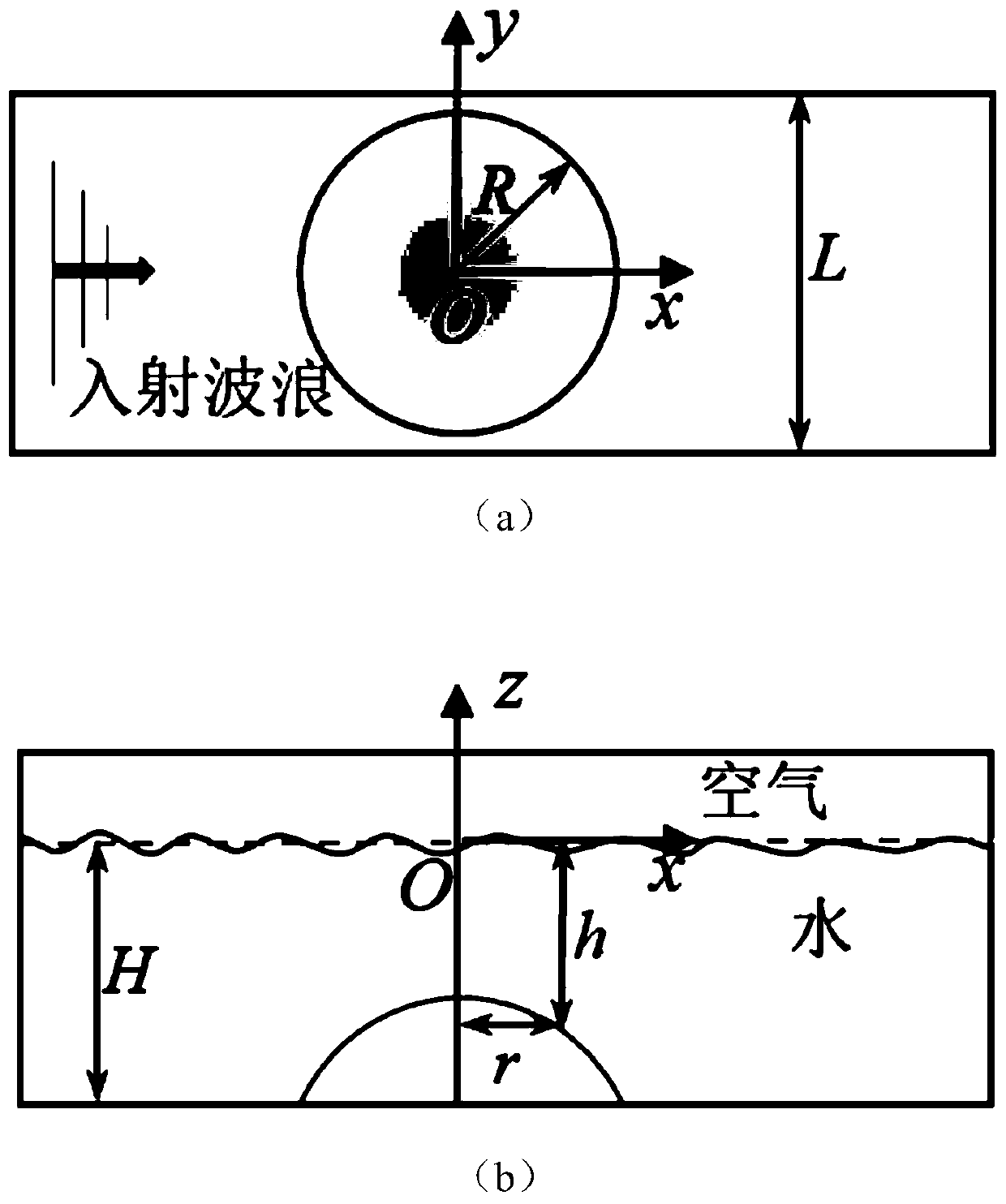
[0040] Such as figure 1 As shown, the method for changing the direction of water wave propagation by setting underwater obstacles provided by this embodiment includes the following steps:

[0041] Step 1. Determine the bottom surface size of the underwater obstacle according to the horizontal span L of the target water area:

[0042] The cross-sections of underwater obstacles in the vertical water depth direction are all concentric circles, the radius of the circle changes with the water depth direction, and the bottom surface radius of underwater obstacles is the largest;

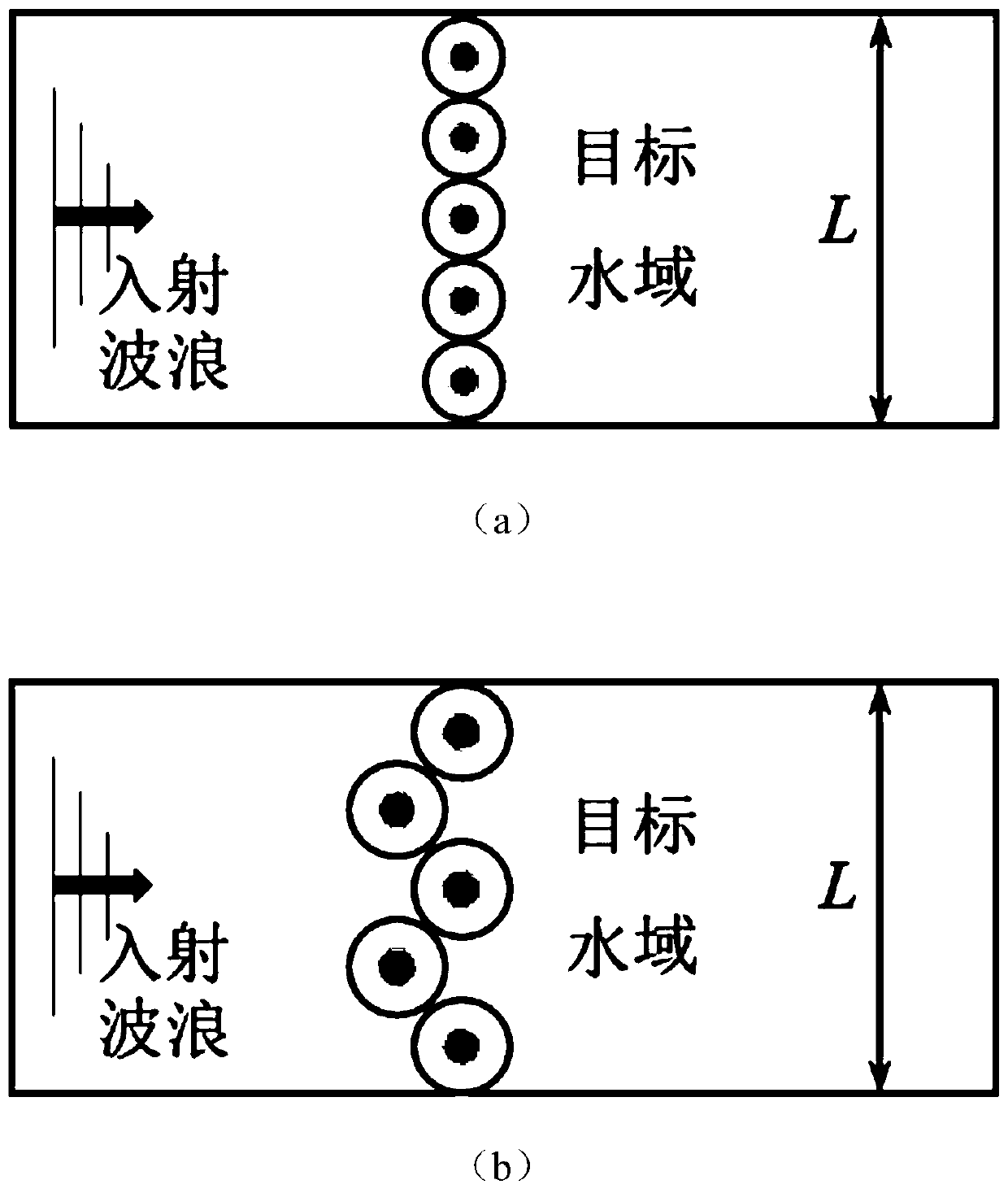
[0043] When only one underwater obstacle is used, the maximum radius R of the underwater obstacle is half of the horizontal span L of the target water area of ​​the underwater obstacle R=L / 2; when the target water area is wide, multiple underwater obstacles are required ...

Embodiment 2

[0067] In the second embodiment, the flow channel is 2m wide, 16m long, the water depth is 0.5m, and the incident water wave frequency is 2.5Hz.

[0068] The method adopted in the second embodiment is basically the same as that in the first embodiment, and only the differences are described here:

[0069] According to the size of the flow channel, it can be known that the maximum water depth is H=0.5m. Considering the limitations of molding technology, we choose the bottom radius of underwater obstacles R = 0.25m.

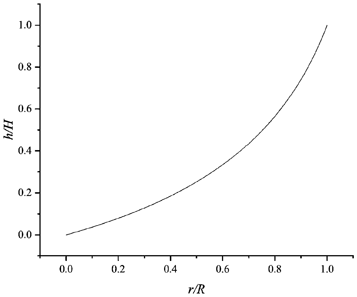
[0070] Taking 21 data points as an example, the data of each point on the busbar of the underwater obstacle is shown in Table 3 below:

[0071] Table 3. Example of busbar data of underwater obstacles in Embodiment 2

[0072]

[0073]

[0074] In the second embodiment, if Figure 6 As shown in (a), it is the generatrix curve of underwater obstacles, and on this basis, the following is designed: Figure 6 The 3D model drawing of the underwater obstacle show...


PUM


Abstract

The invention provides a method for changing water wave propagation direction by arranging an underwater obstacle. The method comprises the steps that 1, the bottom face size of the underwater obstacle is determined according to the horizontal span of a target water area; 2, the specific shape of the underwater obstacle is determined, wherein the number and distribution positions of data points onan underwater obstacle bus are set, and the coordinate values, corresponding to the water depth, of the radius are calculated according to a transformation equation; data calculated according to thetransformation equation is substituted into an underwater obstacle height calculation formula, and then the coordinate values of the data points on the corresponding underwater obstacle bus can be obtained; a bus curve is drawn according to the coordinate values of the data points, the bus curve is rotated by 360 degrees around the central axis to generate a cone, and then the specific shape of the underwater obstacle is obtained; 3, the underwater obstacle is arranged, wherein the underwater obstacle is manufactured based on the data in the step 2, then the underwater obstacle is placed at the water bottom of the upstream of the target water area, the water surface wave propagation direction passing through the underwater obstacle is deflected, and the target water area is protected against the influence of waves.

Description

technical field [0001] The invention belongs to the technical field of water conservancy science and marine engineering, and in particular relates to a method for changing the propagation direction of water waves by setting underwater obstacles. [0002] technical background [0003] Waves may cause beach erosion, endanger the safety of boats and the stability of water structures, and the propagation of waves also has a greater impact on the accumulation of floating objects on the water and the growth of underwater animals and plants. [0004] Water conservancy projects often use engineering measures to build solid, permeable, or floating breakwaters to protect bank slopes. This method is simple in structure and convenient in construction, but it is expensive and affects the landscape and ecological environment. With the strengthening of people's awareness of ecological protection, planting anti-wave forests has also become a trend for beach consolidation and bank protection...

Claims


Application Information

Patent Timeline
Patent Type & Authority Applications(China)
IPC IPC(8): E02B1/00
CPCE02B1/00
Inventor 王思莹丁宁李旭黄明海李利林永水王凯辉焦豹陈威胡五龙
Owner WUHAN UNIV OF TECH
Why Eureka
Try Eureka