
A circulation cooling system for water conservancy and hydropower projects

A technology for circulating heat dissipation, water conservancy and hydropower, applied in indirect heat exchangers, heat exchange equipment, heat exchanger shells, etc., can solve problems such as equipment damage, achieve reasonable structure design, reduce accumulation around heat sinks, and facilitate continuous circulation endothermic effect

Active Publication Date: 2020-12-29
大唐水电科学技术研究院有限公司
View PDF6 Cites 0 Cited by
  • Summary
  • Abstract
  • Description
  • Claims
  • Application Information

AI Technical Summary

Problems solved by technology

[0003] At present, in water conservancy and hydropower projects, due to the high temperature of the oil source used by some equipment after working for a long time, in the absence of replacement of the oil source, high temperature operation is easy to cause damage to the equipment. Therefore, We propose a circulating cooling system for water conservancy and hydropower projects

Method used

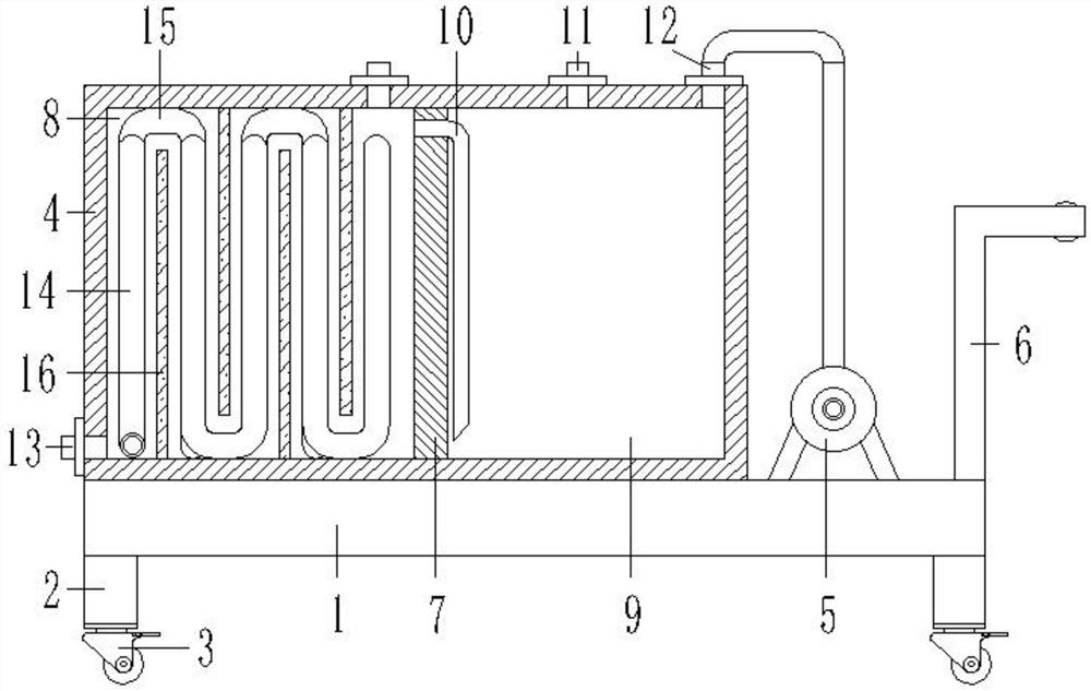
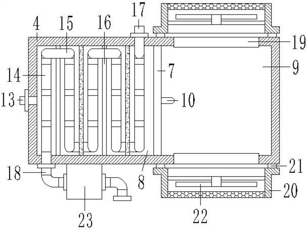
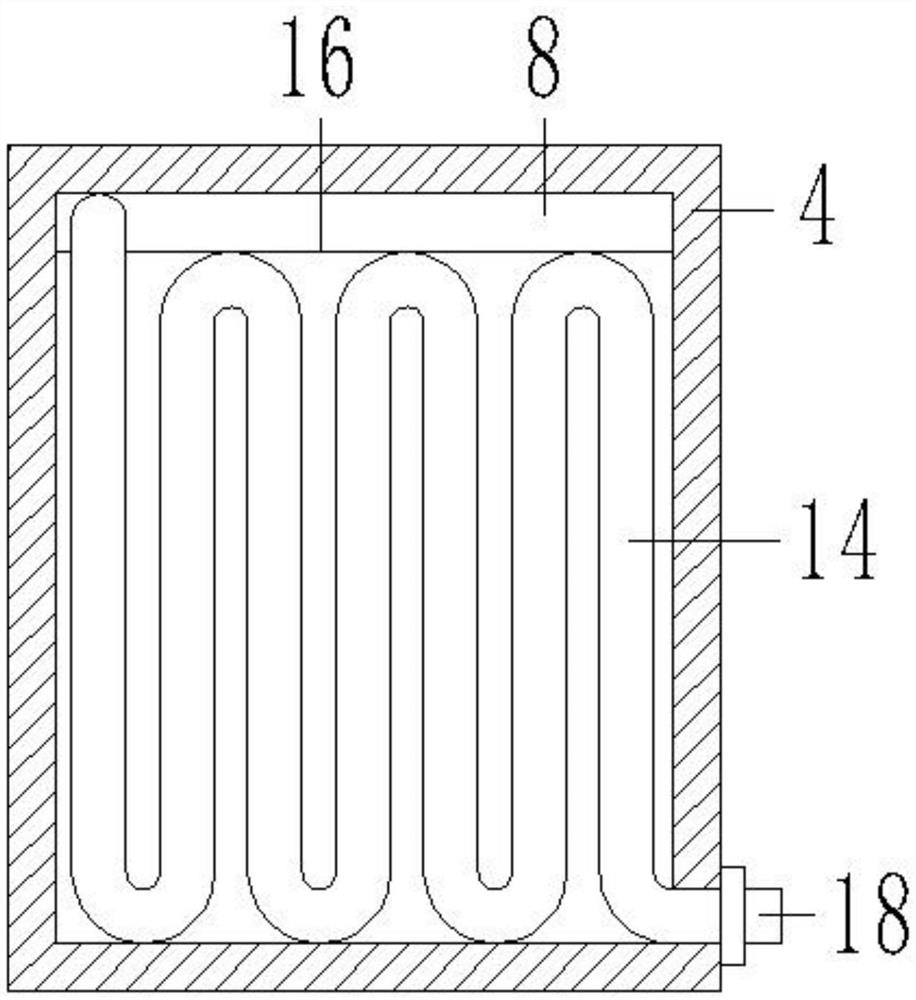

Image

  • A circulation cooling system for water conservancy and hydropower projects
  • A circulation cooling system for water conservancy and hydropower projects
  • A circulation cooling system for water conservancy and hydropower projects

Examples


Embodiment Construction

[0024] The following will clearly and completely describe the technical solutions in the embodiments of the present invention with reference to the accompanying drawings in the embodiments of the present invention. Obviously, the described embodiments are only some, not all, embodiments of the present invention. Based on the embodiments of the present invention, all other embodiments obtained by persons of ordinary skill in the art without creative efforts fall within the protection scope of the present invention.

[0025] see Figure 1-3 As shown, a circulating heat dissipation system for water conservancy and hydropower projects includes a base 1, the four corners of the bottom of the base 1 are fixed with foot blocks 2, the bottoms of the four sets of foot blocks 2 are all provided with universal rollers 3, and the top of the base 1 starts from the left To the right, a heat dissipation box 4, a water pump 5 and a push handle frame 6 are arranged in turn, and the push handle...


PUM


Abstract

The invention discloses a circulating heat dissipation system for water conservancy and hydroelectricity engineering. The circulating heat dissipation system for the water conservancy and hydroelectricity engineering involves a base, wherein the top of the base is sequentially provided with a heat dissipation box body, a water pump and a hand-pushing frame from left to right, a partitioning plateis fixedly connected to an inner cavity of the heat dissipation box body, the inner cavity of the heat dissipation box body is partitioned into a heat dissipation chamber and a cooling anti-freezing fluid chamber through the partitioning plate, a circulating pipe is arranged at the top of the right side wall of the partitioning plate, liquid injecting pipes are arranged at the top of an inner cavity of the heat dissipation chamber and the top of an inner cavity of the cooling anti-freezing fluid chamber in a communicating mode correspondingly, a liquid inlet pipe is arranged on the right sideof the top of the heat dissipation box body, a liquid outlet pipe is arranged at the bottom of the left side wall of the heat dissipation box body, S-shaped heat dissipation pipes are arranged in theinner cavity of the heat dissipation box body at equal intervals from left to right, a flow guiding plate is arranged between every adjacent two groups of the S-shaped heat dissipation pipes, a wateroutlet pipe is arranged on the rear side wall of the heat dissipation box body, and a water inlet pipe is arranged on the front side wall of the heat dissipation box body. The circulating heat dissipation system is reasonable in structural design, facilitates timely and effectively auxiliary circulating heat dissipation of oil sources, and reduces damage to equipment under the high-temperature operation of the system.

Description

technical field [0001] The invention relates to the technical field of water conservancy and hydropower engineering, in particular to a circulating cooling system for water conservancy and hydropower engineering. Background technique [0002] Water Conservancy and Hydropower Engineering Cultivate senior engineering and technical personnel who have the knowledge of surveying, planning, design, construction, scientific research and management of water conservancy and hydropower projects, and can be engaged in planning, design, construction, scientific research and management in water conservancy, hydropower and other departments , students majoring in water conservancy and hydropower engineering mainly study the basic theories and basic knowledge of mathematics, mechanics and building structures necessary for the construction of water conservancy and hydropower projects, so that students can obtain the necessary basic training in engineering design methods, construction managem...

Claims


Application Information

Patent Timeline
Patent Type & Authority Patents(China)
IPC IPC(8): F28D21/00F28F9/007F28F9/00F28F9/22F28F19/01
CPCF28D21/00F28F9/005F28F9/007F28F9/22F28F19/01
Inventor 曾凡胜黄灿成张新华蒋亮银涛候玉成吴智丁戴俊何东阳
Owner 大唐水电科学技术研究院有限公司
Learn More