

fluid line
A fluid pipeline and fluid technology, which is used in machine/engine, crankcase ventilation, mechanical equipment, etc., and can solve the problems of reduced dimensional accuracy of orifices and insufficient air tightness of partition walls.
- Summary
- Abstract
- Description
- Claims
- Application Information
AI Technical Summary
Problems solved by technology
Method used
Image

Examples
Embodiment Construction
[0020] Embodiments of the present invention will be described below based on the drawings.
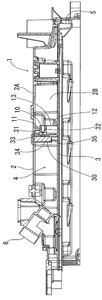
[0021] exist figure 1 The overall structure of the fluid line 1 in the embodiment of the present invention is shown in . As shown in the figure, a fluid line 1 is formed by combining an upper member 2 and a lower member 3, and a fluid passage 4 is formed in a region surrounded by the two members. In this embodiment, the fluid line 1 is a blow-by gas line provided in the engine of the vehicle, and the blow-by gas (gas leaked from the combustion chamber of the engine) flows from a channel provided on the upstream side of the lower member 3 . The fluid is introduced into the opening end 5 , passes through the fluid passage 4 , and is discharged from the opening end 6 provided on the downstream side of the upper member 2 . In addition, the upper member 2 is a member integrated with the cylinder head cover of the engine, and has a top wall 2A and side walls 2B on both sides.
[0022] A p...
PUM
 Abstract
Description
Claims
Application Information