
Heat exchangers for motor vehicles

A technology for heat exchangers and motor vehicles, applied in heat exchange equipment, indirect heat exchangers, heat exchanger types, etc., can solve problems such as unsatisfactory results, reduce production defects, reduce production costs, and avoid leakage Effect

Active Publication Date: 2021-08-17
VALEO AUTOSYSTY
View PDF7 Cites 0 Cited by
  • Summary
  • Abstract
  • Description
  • Claims
  • Application Information

AI Technical Summary

Problems solved by technology

Various attempts have been made to solve this problem, but the results are not satisfactory

Method used


Image

  • Heat exchangers for motor vehicles
  • Heat exchangers for motor vehicles
  • Heat exchangers for motor vehicles

Examples


Embodiment Construction

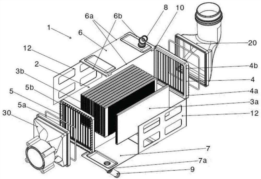
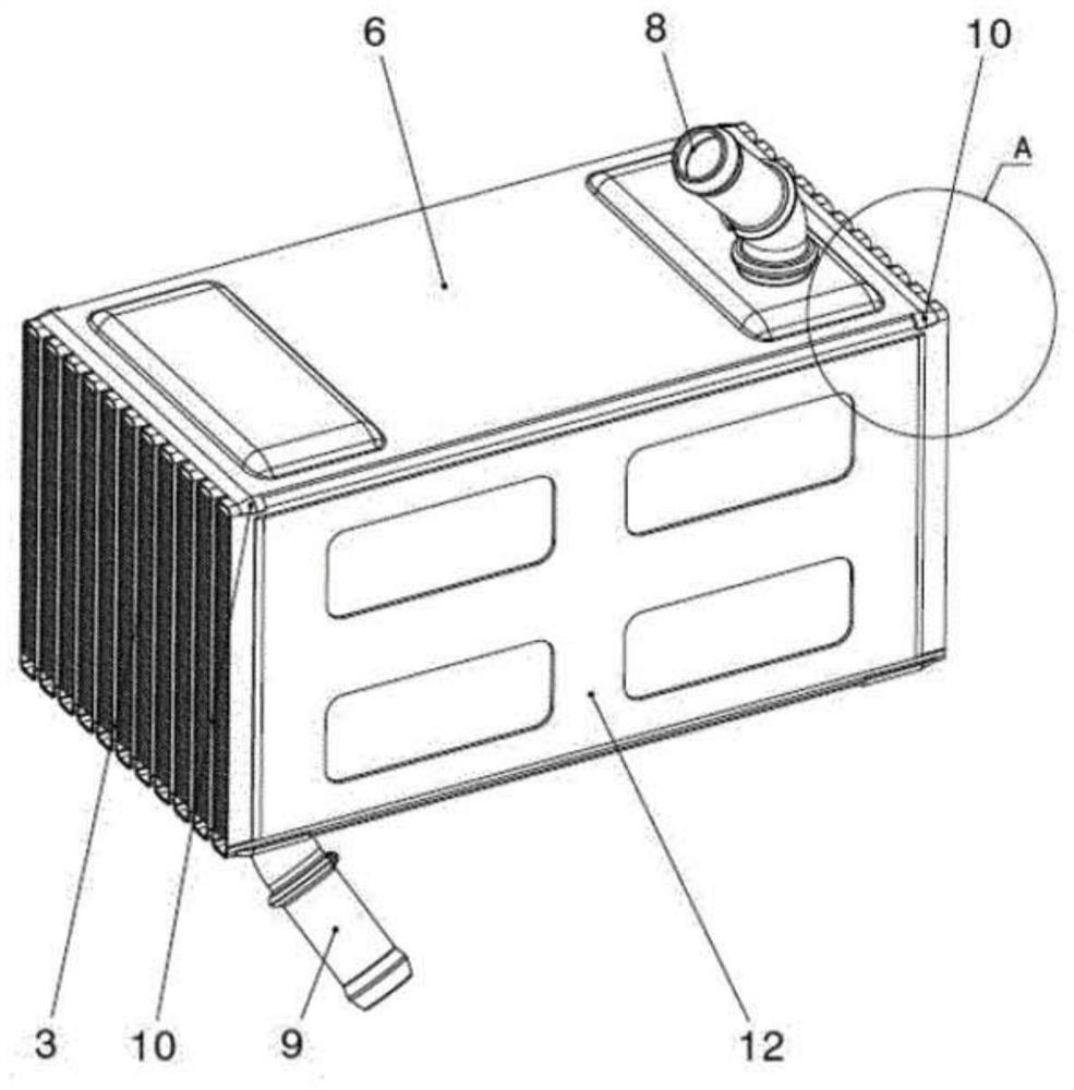
[0018] Such as figure 1 The shown heat exchanger 1 designed for a motor vehicle comprises a core 2 formed from a tube bundle with a plurality of flat tubes 3 for guiding the gas to be cooled in the heat exchanger 1 , in particular air. The flat tubes 3 have defined larger side surfaces and their smaller side surfaces, the larger side surfaces of which are arranged parallel to each other and at a distance from each other to form channels for guiding the cooling fluid therebetween. The tube bundle includes a first extreme tube 3a and a second extreme tube 3b located on both sides of the remaining tubes 3 of the tube bundle, respectively.

[0019] The tubes 3 , 3 a , 3 b of the core 2 are gas-tightly connected on one side of their open ends with an inlet header 4 through which cooling gas is delivered from the hot gas inlet channel 20 . The tubes 3 , 3 a , 3 b are airtightly connected at the other opposite side of their open ends to an outlet header 5 from which cooling gas is d...


PUM


Abstract

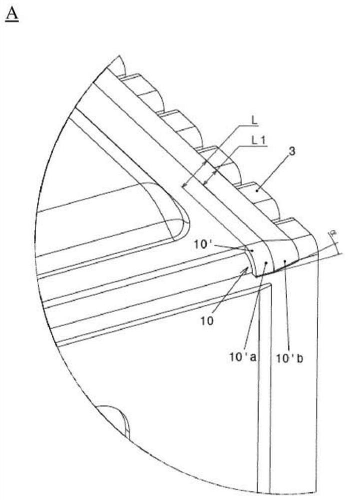
The invention relates to a heat exchanger for a motor vehicle comprising: a core (2) comprising a tube bundle of open-ended stacked tubes (3) and comprising top and bottom extreme tubes (3a, 3b); headers (4 , 5), each header has a shaped flange (4a, 5a) with corners (4b, 5b), and is connected with the open end of the tube (3, 3a, 3b); and the side housing part (6 , 7) located on opposite sides of the core (2) and extending at least partially between the extreme tubes (3a, 3b) and between the header tubes (4, 5). At least one side shell part (6, 7) has at least one protrusion (10) protruding from the side shell part (6, 7) in its corner and bent to contact the side surface of the tube bundle; at least one protrusion (10) has an outer surface (10') opposite the tube bundle and formed to match the profile shape of the flange (4a, 5a) of the header (4, 5) in the header corner (4b, 5b) wherein the outer surface (10') of at least one protrusion (10) abuts the flange (4a, 5a) of the header (4, 5) to ensure that the header (4, 5) is at its corner The parts (4b, 5b) are in liquid-tight connection with the flanges (4a, 5a).

Description

technical field [0001] The invention relates to a heat exchanger for a motor vehicle. Background technique [0002] Heat exchangers used in motor vehicles are designed to cool the combustion air supplied to the engine to improve engine efficiency. A typical heat exchanger includes a core made up of a tube bundle comprising flat tubes that are parallel to and spaced apart from each other and whose open opposite ends are attached to headers to supply and exhaust air to the individual tubes. The headers are connected to the inlet and outlet connector tubes, respectively. On the sides of the core are placed side housing parts which include inlets and outlets for cooling liquid, usually water. The side housing sections, together with the extreme core tubes and headers, form a liquid-tight housing in which a coolant circulates around the air ducts, cooling the air passing therethrough. After the heat exchanger is assembled, the faces of the extreme tubes and headers and the edg...

Claims


Application Information

Patent Timeline
Patent Type & Authority Patents(China)
IPC IPC(8): F28F9/02F28D7/16F28D21/00
CPCF28D7/1684F28D2021/0082F28F9/0219F28F2225/02F28F2265/16F02B29/0462F28F9/001
Inventor B.库洛夫斯基M.克鲁塞克R.比尼克R.乔奇克
Owner VALEO AUTOSYSTY
Learn More