Heat transfer coefficient detection heating device and heat transfer coefficient detection device

A heating device and heat transfer coefficient technology are applied in the fields of heat transfer coefficient detection heating devices and heat transfer coefficient detection devices, which can solve the problems of inconvenient detection, complicated structure of the heat transfer coefficient detection device, etc. Simple to use effects

Pending Publication Date: 2018-06-29
ZHANJIANG JIANKE ENG QUALITY TESTING CENT CO LTD
View PDF0 Cites 2 Cited by
  • Summary
  • Abstract
  • Description
  • Claims
  • Application Information

AI Technical Summary

Problems solved by technology

[0004] Therefore, the technical problem to be solved by the present invention is to overcome the defects of complex structure and inconvenient detection of the heat transfer coefficient detection device in the prior art, thereby providing a heat transfer coefficient detection heating device and a heat transfer coefficient detection device with a simple structure and convenient detection. Detection device

Method used


Image

  • Heat transfer coefficient detection heating device and heat transfer coefficient detection device
  • Heat transfer coefficient detection heating device and heat transfer coefficient detection device
  • Heat transfer coefficient detection heating device and heat transfer coefficient detection device

Examples


Embodiment 1

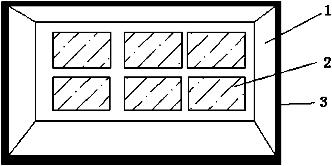
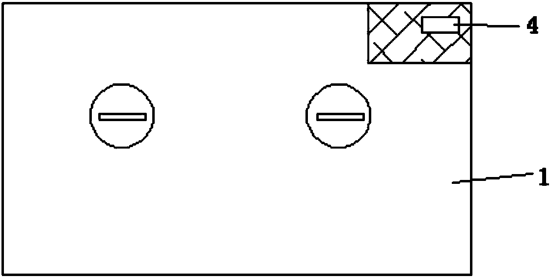
[0041] like Figure 1-3Shown is a specific implementation of a heat transfer coefficient detection heating device, including a box 1 with a length of 2 m, a height of 1 m, and a depth of 0.5 m. The box body 1 includes a box body with an outer layer and an inner layer and forms In the cavity inside the box body, the inner and outer layers of the box 1 are made of wear-resistant aluminum materials, and the outer layer and the inner layer of the box 1 are filled with heat insulating materials , the opening end of the box 1 is provided with a rubber sealing strip 3, and the film heater 2 as a heating device is arranged on the inner wall of the cavity, and the cavity is provided with a temperature collector for collecting the temperature in the box 1. The monitoring probe, the microcontroller is integrated on an inner wall of the cavity, the box body is provided with a card slot, the card slot is connected with the microcontroller, and the phone card is inserted into the card slot ...

Embodiment 2

[0044] This embodiment is a specific implementation of a heat transfer coefficient detection device, including a heat transfer coefficient detection heating device provided in Embodiment 1, a heat flow meter plate, and a temperature testing instrument located on the outer surface of the enclosure.

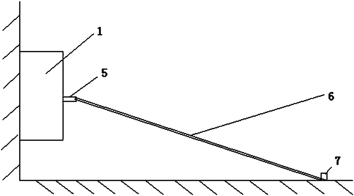
[0045] During detection, after the calorimeter plate is attached to the inner surface of the maintenance structure in the box body 1 with adhesive tape, the box body 1 is fixed to the inner surface of the maintenance structure by the method in embodiment 1, and the box body 1 is heated to After the target temperature, record the temperature inside and outside the envelope, the temperature of the inner surface of the envelope, the temperature of the outer surface, and the value of the heat flow meter plate, calculate the heat transfer coefficient according to the heat transfer coefficient formula, and record multiple sets of data to calculate the average value.


PUM


Abstract

The invention provides a heat transfer coefficient detection heating device and a heat transfer coefficient detection device. The heat transfer coefficient detection heating device comprises a box anda heating device, wherein the box comprises a box body and a cavity; the cavity is formed in the box body; the opening end of the box body is in sealed connection with the inner surface of a to-be-detected enclosure structure; the heating device is arranged in the box. The heat transfer coefficient detection heating device has the advantages that when the heat transfer coefficient of the enclosure structure of a building is detected by a heat flow meter, the opening end of the box body is in sealed connection with the inner surface of the to-be-detected enclosure structure, the interior of the box is heated by the heating device, the temperature in the box is 10 DEG C higher than the temperature of the outer side of the enclosure structure, and then the heat transfer coefficient can be detected; the structure is simple, the handling of air conditioners at site is not needed, the working efficiency is greatly improved, the indoor heating is also not needed, the operation is simple, andthe heat transfer coefficient can be detected in all seasons.

Description

technical field [0001] The invention relates to the technical field of heat transfer coefficient detection, in particular to a heat transfer coefficient detection heating device and a heat transfer coefficient detection device. Background technique [0002] The wall is the main part of the building envelope, and the detection of the wall heat transfer coefficient is one of the important detection items. The heat transfer coefficient K of the wall is the heat transferred through the wall area per square meter per unit time when the wall (including all structural layers) is under stable heat transfer conditions when the air temperature difference on both sides is 1K (1°C). . The conventional on-site detection method is the heat flow meter method, and the heating method used on site is to install air conditioners and oil heaters for heating, or use air conditioners for cooling in summer. According to the requirements of the standard: the surface temperature of the high-temper...

Claims


Application Information

Patent Timeline
IPC IPC(8): G01N25/20G01N25/18
CPCG01N25/18G01N25/20
Inventor 眭斌
Owner ZHANJIANG JIANKE ENG QUALITY TESTING CENT CO LTD
Why Eureka
Try Eureka