Power device and welding positioning method thereof

A power device and limit protrusion technology, which is applied to electrical components, workpiece edge parts, and electrical components to assemble printed circuits, etc., can solve the problems of low reliability, complicated production process, tool wear, etc., to avoid tool wear, The effect of improving welding consistency and welding quality

Inactive Publication Date: 2020-04-03
GREE ELECTRICHEFEI +1
View PDF4 Cites 0 Cited by
  • Summary
  • Abstract
  • Description
  • Claims
  • Application Information

AI Technical Summary

Problems solved by technology

[0002] With the national strategic policy of energy saving, emission reduction and green environmental protection, the company's full frequency conversion planning development direction, more and more frequency conversion products will become the company's mainstream; but its production process is complicated, and the production efficiency is low. In the production process of the core power device of the frequency conversion external unit, our company requires the positioning accuracy of the power module to be ≤±0.3mm, and the assembly method is fixed by the gasket tooling method, but tooling wear, foreign objects and other abnormalities will easily lead to abnormal positioning accuracy of the module, and reliability lower

Method used


Image

  • Power device and welding positioning method thereof
  • Power device and welding positioning method thereof
  • Power device and welding positioning method thereof

Examples


Embodiment 1

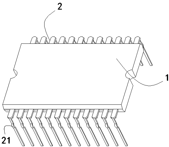
[0037] Such as Figure 1-4 As shown, the embodiment of the present invention provides a welding positioning method for power devices, including the following steps:

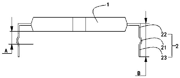
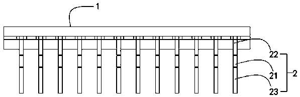
[0038] (a) Select the power device: According to the needs of the production model, select the power device suitable for the production model; the power device is composed of a power device body 1 and a plurality of pins 2, and the pin 2 is set to limit the power device The limit protrusion 21 of the installation height of the body 1, further, the height B of the pin 2 is 11 mm, the height A between the end face of the power device body 1 and the end of the limit protrusion 21 is 6.0 mm, and the height of the pin 2 The number is 24, and pin 2 is IPM material pin 2.

[0039] (b) Plug-in positioning: Insert the pin 2 on the power device selected in step (a) directly into the PCB board 3 of the production model, and make the power device body 1 through the limit protrusion 21 on the pin 2 The height between the po...

Embodiment 2

[0042] Such as Figure 1-4 As shown, the embodiment of the present invention provides a welding positioning method for power devices, including the following steps:

[0043] (a) Select the power device: According to the needs of the production model, select the power device suitable for the production model; the power device is composed of a power device body 1 and a plurality of pins 2, and the pin 2 is set to limit the power device The limit protrusion 21 of the installation height of the body 1, further, the height B of the pin 2 is 12.2 mm, the height A between the end face of the power device body 1 and the end of the limit protrusion 21 is 7.2 mm, the pin 2 The number is 25, and pin 2 is IPM material pin 2.

[0044] (b) Plug-in positioning: Insert the pin 2 on the power device selected in step (a) directly into the PCB board 3 of the production model, and make the power device body 1 through the limit protrusion 21 on the pin 2 The height between the power device body ...

Embodiment 3

[0047] Such as Figure 1-4 As shown, the embodiment of the present invention provides a welding positioning method for power devices, including the following steps:

[0048](a) Select the power device: According to the needs of the production model, select the power device suitable for the production model; the power device is composed of a power device body 1 and a plurality of pins 2, and the pin 2 is set to limit the power device The limit protrusion 21 of the installation height of the body 1, further, the height B of the pin 2 is 14.5 mm, the height A between the end face of the power device body 1 and the end of the limit protrusion 21 is 9.5 mm, and the pin 2 The number is 30, and pin 2 is IPM material pin 2.

[0049] (b) Plug-in positioning: Insert the pin 2 on the power device selected in step (a) directly into the PCB board 3 of the production model, and make the power device body 1 through the limit protrusion 21 on the pin 2 The height between the power device bo...


PUM

PropertyMeasurementUnit
heightaaaaaaaaaa

Abstract

The invention provides a power device which comprises a power device body, wherein two ends of the power device body are fixedly provided with a plurality of pins, and the pins are provided with limiting bulges used for limiting the installation height of the power device body. The power device can be directly inserted into a PCB for welding and fixing production, which not only eliminates the positioning height of an original gasket tool, but also improves the production efficiency and the quality consistency of the production line.

Description

technical field [0001] The invention relates to the field of production technology of frequency converters, in particular to a welding positioning method for power devices. Background technique [0002] With the national strategic policy of energy saving, emission reduction and green environmental protection, the company's full frequency conversion planning development direction, more and more frequency conversion products will become the company's mainstream; but its production process is complicated, and the production efficiency is low. In the production process of the core power device of the frequency conversion external unit, our company requires the positioning accuracy of the power module to be ≤±0.3mm, and the assembly method is fixed by the gasket tooling method, but tooling wear, foreign objects and other abnormalities will easily lead to abnormal positioning accuracy of the module, and reliability lower. Contents of the invention [0003] In view of this, the ...

Claims


Application Information

Patent Timeline
Patent Type & Authority Applications(China)
IPC IPC(8): B23K33/00H05K3/30H05K3/34
CPCB23K33/00H05K3/306H05K3/3447
Inventor 尹新新李敏郭磊徐蒙孙金郭海生
Owner GREE ELECTRICHEFEI
Why Eureka
Try Eureka