Overturning locating clamp disk and clamp table

A technology for positioning fixtures and fixture disks, which is applied to positioning devices, clamping, manufacturing tools, etc. It can solve the problems of easily damaged and scratched products, difficult handling and flipping, and inability to standardize operations, so as to achieve easy flipping and adjustment of positions and angles, good shape and structural stability, good handling and stability

Pending Publication Date: 2020-04-03
SUZHOU BRIDGE ELECTRONICS
View PDF0 Cites 0 Cited by
  • Summary
  • Abstract
  • Description
  • Claims
  • Application Information

AI Technical Summary

Problems solved by technology

In the existing technology, the size of the product processed on the machine tool is relatively large, and it is necessary to perform multi-point clamping to limit the material in order to obtain relatively good processing stability during the processing process. In the fixing method, it is easy to produce stress and deformation, and the fixing accuracy is not high, which will affect the processing quality.
In addition, due to the large size and weight of the product, many people are required to cooperate with manual operations to complete the product handling and flipping actions. The handling and flipping are difficult, the production efficiency is low, the production quality cannot be guaranteed, and the product is easy to be damaged and scratched, and even lead to scrapping In the process of handling and turning, personnel are prone to fatigue, and are prone to risks such as crushing injuries and muscle strains, and it is time-consuming and labor-intensive, making it impossible to standardize operations

Method used


Image

  • Overturning locating clamp disk and clamp table
  • Overturning locating clamp disk and clamp table
  • Overturning locating clamp disk and clamp table

Examples


Embodiment Construction

[0039] The present invention will be described in detail below in conjunction with various embodiments shown in the drawings. However, these embodiments do not limit the present invention, and structural, method, or functional changes made by those skilled in the art according to these embodiments are included in the protection scope of the present invention.

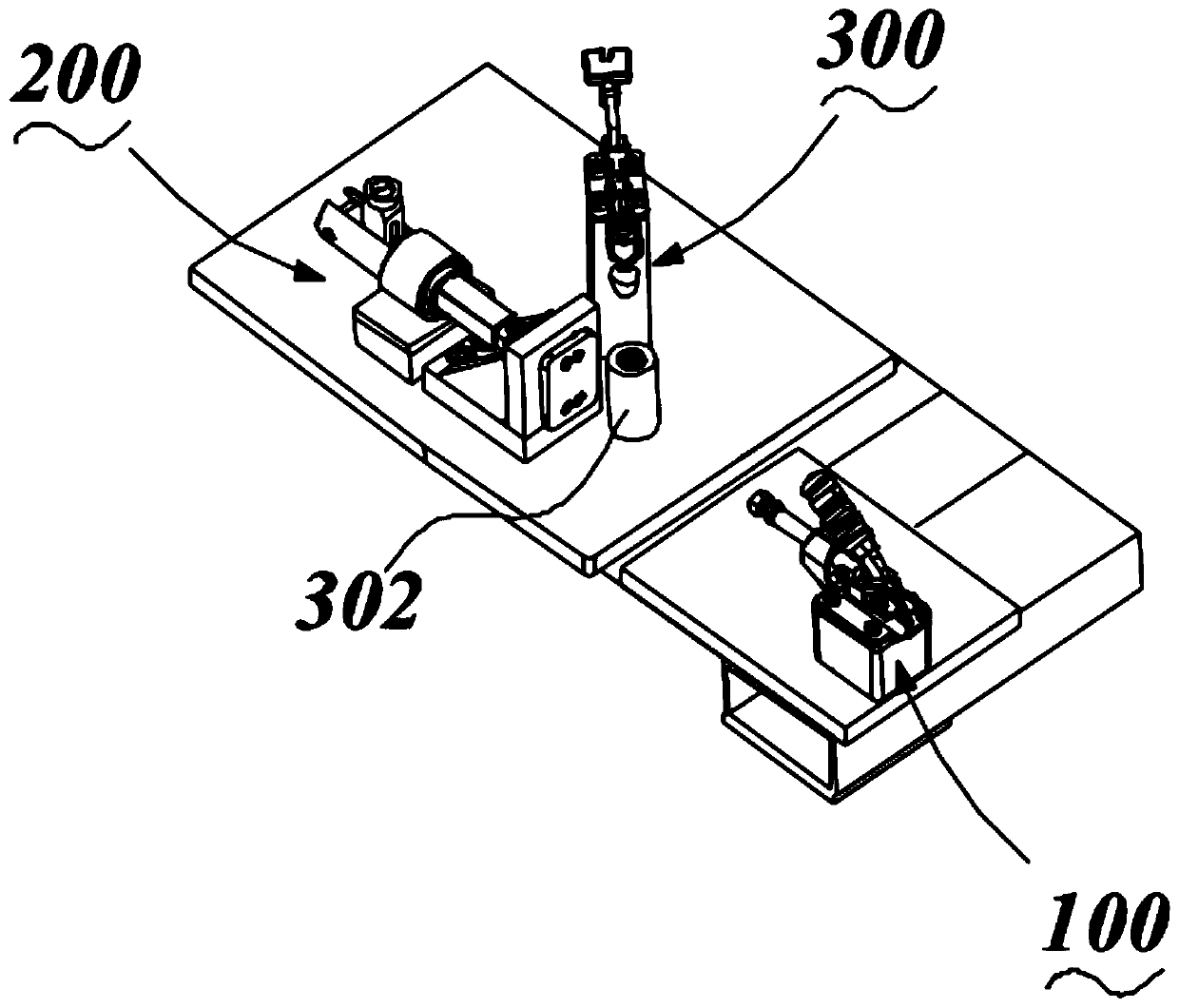
[0040] The flip positioning fixture disk disclosed by the present invention includes several first positioning fixtures 100, several second positioning fixtures 200 and several third positioning fixtures 300, such as figure 1 In the situation shown, each set of positioning jigs includes a combination of the first positioning jig 100, the second positioning jig 200 and the third positioning jig 300, and each positioning jig in the jig set includes a clamping end. The main body (the main body refers to the part of the positioning fixture other than the clamping end, the same below), wherein there are at least two main bod...


PUM


Abstract

The invention discloses an overturning locating clamp disk and a clamp table. The overturning locating clamp disk comprises a plurality of locating clamp sets and a clamp disk. The locating clamp setsare arranged on the clamp disk. A rotating shaft is arranged on a pair of side portions of the clamp disk body. Each locating clamp set comprises a plurality of locating clamps, a plurality of secondlocating clamps and a plurality of third locating clamps, wherein each locating lamp comprises a body with a clamping end. The bodies of at least two locating clamps are on the same side of the clamping ends, and the clamping ends of the locating clamps are arranged adjacently in the same direction; or, the bodies of at least two clamping clamps are on the different sides of the clamping ends, and the clamping ends are oppositely arranged. The locating clamps are the first locating clamps or the second locating clamps or the third locating clamps. According to the overturning locating clamp disk and the clamp table, the clamping capacity at multiple angles in multiple directions is provided through the clamp sets, so that a workpiece has good stability in the machining process, the clamptable has the capacity to turn over at will, and then the operation convenience is quite high.

Description

technical field [0001] The invention belongs to the technical field of machining auxiliary positioning including welding, turning, milling, etc., and specifically relates to a flipping and positioning fixture disc and a fixture table. Background technique [0002] The device used to fix the processing object in the process of mechanical manufacturing so that it occupies the correct position to accept construction or inspection, also known as fixture. In a broad sense, any process in the process, the device used to install the workpiece quickly, conveniently and safely, can be called a fixture. Such as welding fixtures, inspection fixtures, assembly fixtures, machine tool fixtures, etc. Among them, machine tool fixtures are the most common, often referred to as fixtures. When processing a workpiece on a machine tool, in order to make the surface of the workpiece meet the technical requirements such as the size, geometric shape, and mutual position accuracy with other surfac...

Claims


Application Information

Patent Timeline
IPC IPC(8): B23Q3/06B23Q7/00
CPCB23Q3/06B23Q7/00
Inventor 王成吴志伟
Owner SUZHOU BRIDGE ELECTRONICS
Why Eureka
Try Eureka